32
(a) Minimum cable section AWG18 (0.75 mm
2
).
(b)The thermistor cable are delivered with the unit
:
if the current of the load is large, an AC contactor is needed.
1
2
3
4
5
9
10
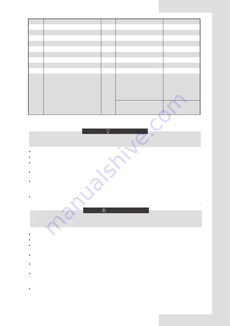
Description
AC/DC
Required number of conductors
Maximum running current
Item
DHW pump control cable
SV2: 3-way valve control cable
SV1: 3-way valve control cable
Booster heater control cable
Room thermostat cable
User interface cable
Solar energy kit signal cable
AC
2
200mA
AC
5
200mA
AC
2
200mA(a)
AC
2
3
200mA(a)
AC
200mA(a)
AC
3
200mA(a)
AC
2
200mA(a)
Power supply cable for indoor unit
AC
6
7
8
Outside circulation pump control cable
Solar pump control cable
AC
2
200mA(a)
AC
2
200mA(a)
Equipment must be grounded.
All high-voltage external load, if it is metal or a grounded port, must be grounded.
All external load current is needed less than 0.2A, if the single load current is greater than 0.2A, the load must be controlled
through AC contactor.
"AHS1" "AHS2", "A1" "A2", "R1" "R2" and "DFT1" "DFT2" wiring terminal ports provide only the switch signal.
Please refer to image of
8.8.6 to get the ports position in the unit.
Plate heat exchanger E-Heating tape and Flow switch E-Heating tape share a control port.
Please use H07RN-F for the power wire, all the cables are connect to high voltage except for thermistor cable and cable
for user interface.
NOTE
Switch off all power including the unit power supply and backup heater and domestic hot water tank power supply (if
applicable) before removing the switch box service panel.
WARNING
Field wiring guidelines
Most field wiring on the unit is to be made on the terminal block inside the switch box. To gain access to the terminal block,
remove the switch box service panel.
8.8.3 Precautions on wiring of power supply
Fix all cables using cable ties.
A dedicated power circuit is required for the backup heater.
Installations equipped with a domestic hot water tank (field supply) require a dedicated power circuit for the booster heater.
Please refer to the domestic hot water tank Installation & Owner's Manual.
Lay out the electrical wiring so that the front cover does not rise up when doing wiring work and attach the front cover
securely.
Follow the electric wiring diagram for electrical wiring works (the electric wiring diagrams are located on the rear side of door
2.
Install the wires and fix the cover firmly so that the cover may be fit in properly.
Use a round crimp-style terminal for connection to the power supply terminal board. In case it cannot be used due to
unavoidable reasons, be sure to observe the following instructions.
Do not connect different gauge wires to the same power supply terminal. (Loose connections may cause overheating.)
When connecting wires of the same gauge, connect them according to the figure below.
-
-
2+GND
ETHKH06A
ETHKH10A
ETHKH16A
ETHKH06A (3kW heater)
ETHKH10A(3kW heater)
ETHKH16A (3kW heater)
0.4A
0.4A
0.4A
13.5A
13.5A
13.5A
4+GND ETHKH06A (9kW heater)
ETHKH10A (9kW heater)
ETHKH16A (9kW heater)
13.3A
13.3A
13.3A
V.2


