10m
m
10m
m
C
B
D
A
Installation Instructions
A. Precaution
:
1. The travel length of the glass grating scale must be longer than the maximum travel of the machine,
2
. To ensure the graduated glass scale to be installed is reliable, and to avoid any possibility of scale
misalignment, the scale should be installed on machined flat surfaces of the machine wherever possible.
In the case where there are no machined flat surfaces available on the machine, machined flat Blocks
or the stainless steel fillers should be used. Wherever possible the scale ends and the reader head
should be installed on a flat surface.
3
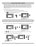
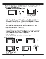
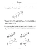
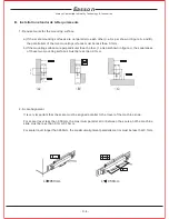
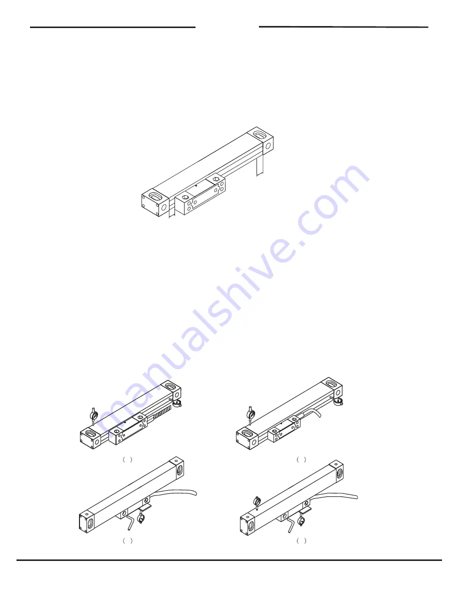
. If a lever dial indicator is used to align the scale, it is important to ensure that the angle between the
dial Indicator lever tip and the surface measured must be less than 30'to avoid a cosine measurement
Error. If a vertical dial indicator is used as per the following figures shown, it is important to ensure
that the dial indicator is perpendicular to the measured surface to also avoid the cosine measurement
error.
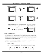
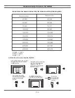
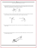
there should be at least 10mm clearance between the ends of the glass scale and the maximum travel
of the machine as per the following figure shown.
¡]
Clearance>10mm
¡^
Always Committed to Quality Technology & Innovation
Easson
- C. 1 -
Summary of Contents for ES-12
Page 8: ...1 Basic Fucntions Basic Functions BASIC...
Page 15: ...8 Built in Calculator Calculator...
Page 27: ...20 REF datum memory...
Page 31: ...24 LHOLE tool positioning for the Line Holes...
Page 35: ...28 INCL Inclined angle tool positioning...
Page 40: ...33 PCD tool positioning for Pitch Circle Diameter...
Page 45: ...R R R 38 tool positioning for ARC machining...
Page 63: ...R R R 56 Simplified R function...
Page 73: ...66 Shrinkage Calculation L L X 1 005...
Page 91: ...Parameter Setup B 1 SET UP...


