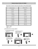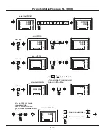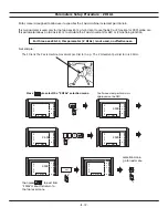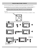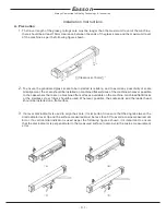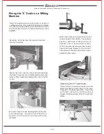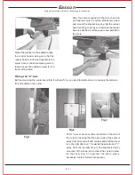
After the scale is aligned to the axis, then drill
and tap the scale to suit the bracket provided
and mount the bracket insuring that the reader
head is sitting correctly so that when the reader
head is attached it will be square and parallel to
the scale.
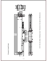
The"z" axis scale should be installed on the side of
the column insuring that the open side of the scale is
away from direct swarf and coolant and that the travel
is in the right direction "-" towards the spindle and "+"
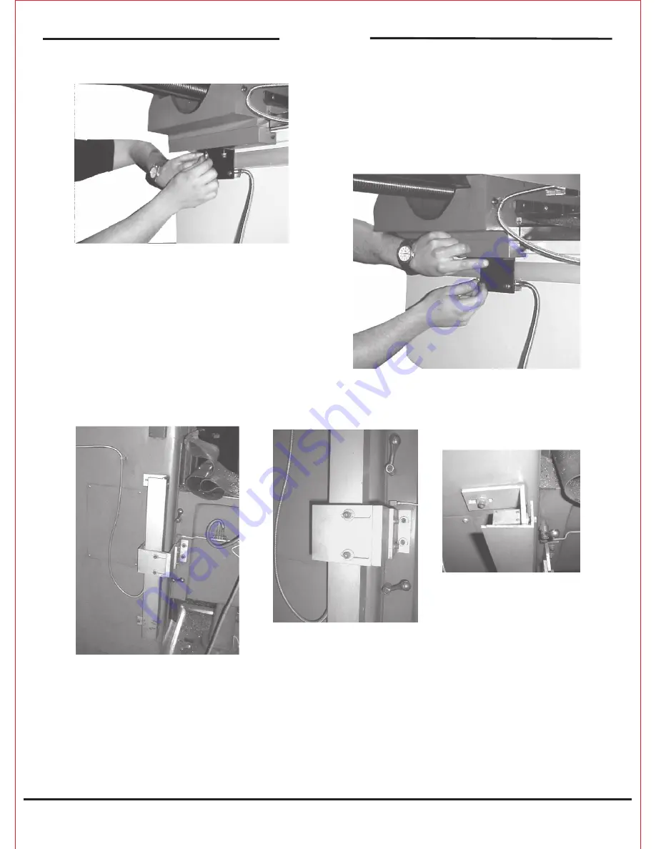
away from the spindle. (Fig.1) The bracket is (Fig 2)
mounted of the knee, and around the scale to allow
f o r t h e c o v e r ( F i g . 3 ) t o p r o t e c t t h e s c a l e w h e r e
excessive coolant & swart are present.
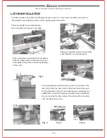
Mount the bracket on the saddle to take
the reader head making sure that the
reader head is in line and parallel to the
scale. Secure the cable making sure to
leave enough free cable to allow for the
travel of the slide.
Fitting the "Z" Axis
Before mounting the scale insure that it will read"+"as you wind the table down, increasing the distance
from the table to the cutter
Fig.1
Fig.2
Fig.3
Always Committed to Quality Technology & Innovation
Easson
- C. 7 -
Summary of Contents for ES-12
Page 8: ...1 Basic Fucntions Basic Functions BASIC...
Page 15: ...8 Built in Calculator Calculator...
Page 27: ...20 REF datum memory...
Page 31: ...24 LHOLE tool positioning for the Line Holes...
Page 35: ...28 INCL Inclined angle tool positioning...
Page 40: ...33 PCD tool positioning for Pitch Circle Diameter...
Page 45: ...R R R 38 tool positioning for ARC machining...
Page 63: ...R R R 56 Simplified R function...
Page 73: ...66 Shrinkage Calculation L L X 1 005...
Page 91: ...Parameter Setup B 1 SET UP...

