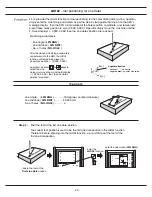
X
Y
Z
ABS
mm
mm
mm
56.785
12.345
45.675
- 30 -
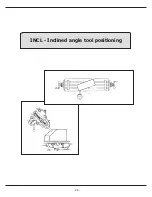
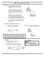
INCL
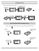
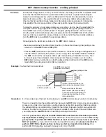
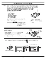
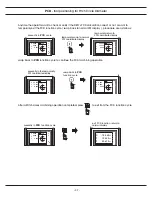
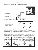
- Inclined angle tool positioning
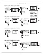
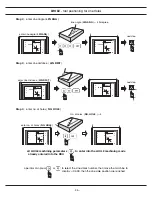
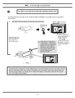
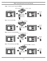
Step 2
: enter the incline angle (
INCL ANG
)
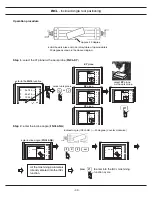
Operation procedure
Step 1
: select the XY plane as the work plane (
INCL-XY
)
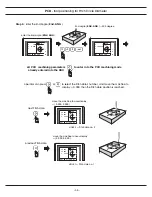
install the work piece onto an rotary table at approximately
20 degree as shown in the above diagram.
approx. 20 degree
enter to the
INCL
function
select work plane
or
XY
plane
XZ
plane
YZ
plane
select
XY
plane
as the work plane
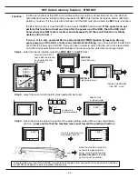
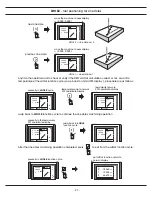
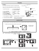
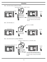
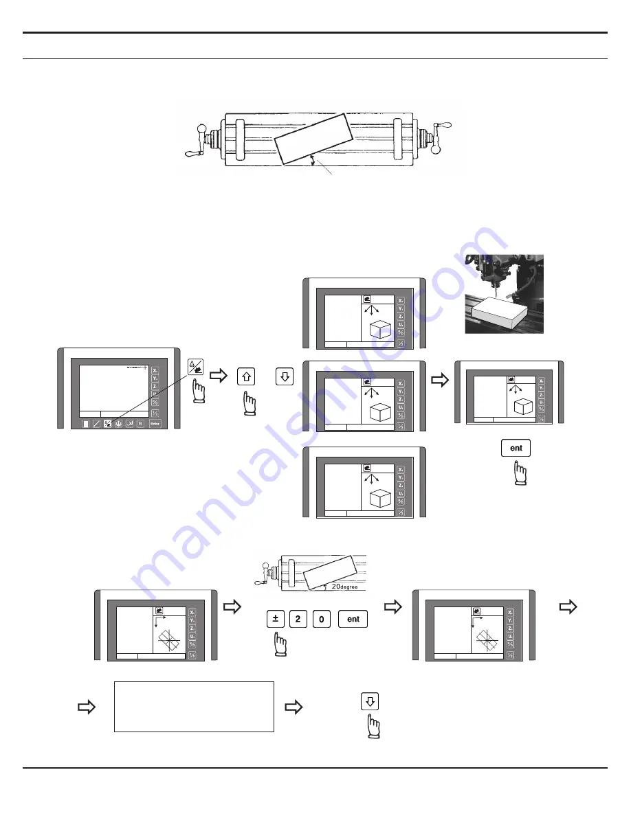
Inclined angle ( INCL ANG ) = -20 degree ( counter clockwise )
enter incline angle (
INCL ANG
)
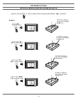
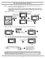
press to enter into the INCL machining
function cycle
all the machining parameters
already entered into the INCL
function,
XY
plane
X
Y
Z
ABS
INCL. XY
INCL.
Y
Z
X
XZ YZ
XY
XY
X
Y
Z
ABS
INCL. XY
INCL.
Y
Z
X
XZ YZ
XY
XY
X
Y
Z
ABS
INCL. XZ
INCL.
Y
Z
X
XZ
XZ YZ
XY
X
Y
Z
ABS
INCL. YZ
INCL.
Y
Z
X
XZ YZ
YZ
XY
X
Y
Z
ABS
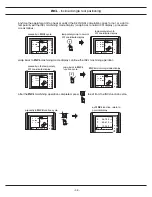
INCL. ANG
0.000
INCL. ANG
INCL.
Y
X
X
Y
Z
ABS
INCL. ANG
-20.000
INCL. ANG
INCL.
Y
X
Summary of Contents for ES-12
Page 8: ...1 Basic Fucntions Basic Functions BASIC...
Page 15: ...8 Built in Calculator Calculator...
Page 27: ...20 REF datum memory...
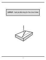
Page 31: ...24 LHOLE tool positioning for the Line Holes...
Page 35: ...28 INCL Inclined angle tool positioning...
Page 40: ...33 PCD tool positioning for Pitch Circle Diameter...
Page 45: ...R R R 38 tool positioning for ARC machining...
Page 63: ...R R R 56 Simplified R function...
Page 73: ...66 Shrinkage Calculation L L X 1 005...
Page 91: ...Parameter Setup B 1 SET UP...

