- A. 2 -
Lathe application
- Axes notation and common practise
Function :
Since the structure of Lathe machine and also the
machining process in lathe is very different from
common vertical or horizontal machines like
milling, boring or drilling machines.
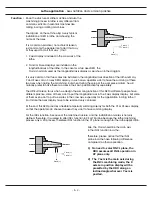
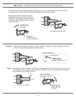
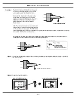
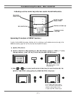
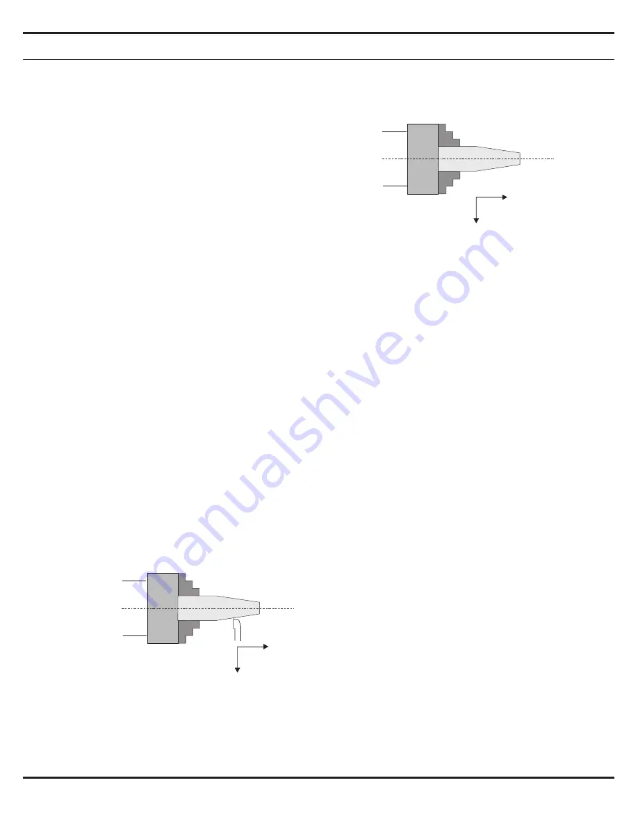
The digram on the Left showing a very typical
installation of DRO in lathe and showing the
name of the axes.
It is a common practise ( no technical reason,
just commonly the people like to do it that way
or they used to do it that way ) that :
1. X axis display is installed in the cross axis of the
lathe.
2. Y and/or Z axes displays are installed in the
longitudinal axis of the lathe. In the case for a two axes DRO, the
Y axis is normally used as the longitudinal axis display as per shown in the diagram.
It is very common that two scales are installed in the longitudinal axis direction of the lathe, let's say
Y and Z axes of an 3 axes DRO's display, in such case, operator want to have the summing of these
two axes when during the machining, but when during the setup of the work piece datum, he will
natually prefer to have these two axes in their own position display seperately.
The difficult mission for us when we design the summing function of this DRO is different people have
different practise, some of them want to put the longitudinal axis in the X axis display display, but some
of them even want to put two scales in the cross axis, especially for the application in a big lathe !!
So it make the axes display have to be summed very confused.
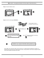
At the end, this DRO provides a flexible temporarily summing display for both the YZ or XZ axes display,
so that the operator can choose the axes they want to have summing display.
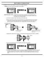
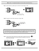
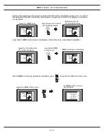
For the INCL function, because of the machine structure, and the installation of scales is not very
defined, therefore, it is useless to offer INCL function in XZ or YZ plane because the lathe machining
process only a 2D process. Therefore INCL function in the XY plane is enough for the lathe application.
Z axis (+)
Y axis (+)
X axis (+)
Z axis (+)
Y axis (+)
X axis (+)
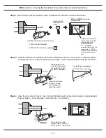
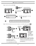
Also, the Y axis should be the main axis
in the INCL function in Lathe.
Therefore, please notice that the INCL
plane in Lathe have following difference
compared to other application.
1) No need to select INCL plane, the
DRO assumes all INCL operation in
XY plane only.
2) The Y axis is the main axis during
the INCL machining mode, the X
axis zero position display will be
presetted by the DRO along an
inclined angle wherever Y axis is
posited.
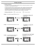
Summary of Contents for ES-12
Page 8: ...1 Basic Fucntions Basic Functions BASIC...
Page 15: ...8 Built in Calculator Calculator...
Page 27: ...20 REF datum memory...
Page 31: ...24 LHOLE tool positioning for the Line Holes...
Page 35: ...28 INCL Inclined angle tool positioning...
Page 40: ...33 PCD tool positioning for Pitch Circle Diameter...
Page 45: ...R R R 38 tool positioning for ARC machining...
Page 63: ...R R R 56 Simplified R function...
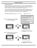
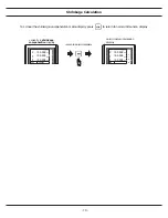
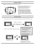
Page 73: ...66 Shrinkage Calculation L L X 1 005...
Page 91: ...Parameter Setup B 1 SET UP...

