21
4. LCD Panel
4.1 Introduction
This chapter introduces the functions and operator instructions of the operator control
and display panel in detail, and provides LCD display information, including LCD
display types, detailed menu information, prompt window information and UPS alarm
information.
4.2 LCD panel for Cabinet
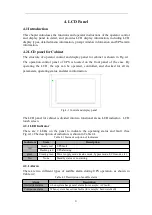
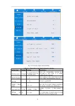
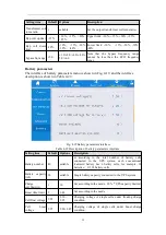
The structure of operator control and display panel for cabinet is shown in Fig.4-1.
The operation control panel of UPS is located on the front panel of the case. By
operating the LCD, the ups can be operated, controlled, and checked for all its
parameters, operating status, and alarm information.
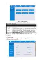
Fig.4-1 Control and display panel
The LCD panel for cabinet is divided into two functional areas
:
LED indicator
,
LCD
touch screen.
4.2.1 LED Indicator
There are 2 LEDs on the panel to indicate the operating status and fault. (See
Fig.4-1).The description of indicators is shown in Table 4.1
Table 4.1 Status description of indicators
Indicators
State
Description
red
Steady red
UPS fault
Flashing red
UPS alarming
green
Steady green Power supply mode (mains mode, bypass mode, ECO mode, etc.)
No
None
Standby status or no starting
4.2.1 Alarm
There are two different types of audible alarm during UPS operation, as shown in
Table 4.2.
Table 4.2 Description of audible alarm
Alarm
Description
Intermittent alarm
when system has general alarm (for example: AC fault),
Continuous alarm
When system has serious faults (for example: hardware fault)
Summary of Contents for EA990 G5 10
Page 2: ......


