13
Connect power cables for parallel UPS units
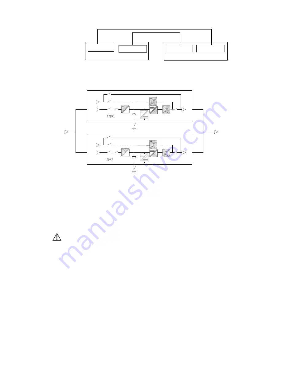
After fully positioning the equipment, use the input and output cable of the parallel system to
respectively connect the input ends of each UPS together, and the output ends of each UPS
together. The wiring schematic diagram is shown as follows.
If using
separate bypass connection, disconnect the short-circuit wire of the bypass input cable L and
the mains input cable L (1-phase in/1-phase out UPS), or the mains input cable C (3-phase
in/1-phase out UPS) inside the terminal block of each UPS. Furthermore, respectively connect the
mains input ends of each UPS together, and the bypass input ends of each UPS together. Pay
attention to confirm whether the live wire and the neutral wire are connected in a correct way.
The cable connection of the battery is the same as that of the single unit. Each UPS has
independent battery pack. UPS cannot share battery packs.
Caution
All of the UPS bypass shall be connected in the same way for power distribution in the parallel
system. The power line between the input end and the AC distribution connecting point of each UPS
shall be as long as that between the output end and the load connecting point. Make sure that the
input and output impedance of each UPS is consistent with each other, so as to achieve the
current-sharing effect of the paralleled UPS.
DB15
公座
DB15
母座
UPS1
DB15
公座
DB15
母座
UPS2
DB15 Male Socket
DB15 Female Socket
DB15 Female Socket
DB15 Male Socket
Load
AC Input
Summary of Contents for 6KVA
Page 1: ......


