background image

EA660 Modular UPS 

User manual & Operation explain


41 

means constant charging. 

2

.

Details information screen


Please refer below


+ -

Ent

Esc


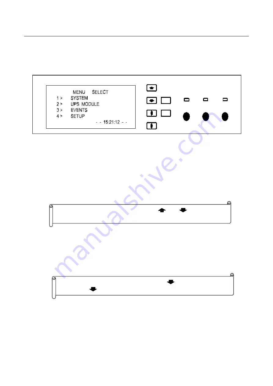
The chart above displays choice menus and it has 4 items. See below:


“SYSTEM”

---------------------------------Display input,output data of the system   

“UPS MODULE”

--------------------------Module’

s ouput voltage, current, temperature data,etc. 

“EVENTS”

---------------------------------Events record of the system 

“SETUP”

-----------------------------------Set the system data

Inclduing time, battery, 

communicationinterface


3. Detailed information screen of system.  

Choose“1 >  SYSTEM” at optional information menu

then press“ENT” to enter detailed 

information screen..It’

s dedivided into3 parts

 and they are

output screen,input screen,battery 

screen. 


Ouput screen interface  is like below


Note

Now

it displays output screen

 and press

key to enter input screen;


press again  

 to enter battery screen. 


Note

Now

at monitoring key-press area,pressing

 / 

,you can move the 

cursor to orientate at any information menu you want to choose.then press 

ENT”. 

Inverter

Bypass

Alarm

On/Off

Ch/Float

Silence

Esc

Ent


Summary of Contents for EA660

Page 1: ...EA660 Modular UPS User manual Operation explain E EA A6 66 60 0 M Mo od du ul la ar r U UP PS S User s Manual ...

Page 2: ... 20 6 1 STATIC SWITCH 20 6 2 MONITORING 21 6 3 SYSTEM MODULAR 22 7 SYSTEM START UP SETUP 23 7 1 START UP PROCEDURE 23 7 1 1 System operating without AC Mains 24 7 1 2 Swich on the battery input switch 24 7 1 3Switch on the AC Mains switch 27 7 1 4 Manual bypass transfesr to the inverter output state 28 7 1 5 Switch on input air breaker of Bypass 30 7 1 6 Checking Phase sequence 31 7 1 7 Transfer m...

Page 3: ...n 11 3 MAINTENANCE BYPASS 53 12 MAINTENANCE 54 12 1 PLEASE CONSIDERTHE CAPACITY AND CHARACTERISTIC OF THELOAD 54 12 2 PROTECT UPS FROM LIGHTNING STRIKE 54 12 3 NOTICE OF MAINTENANCE AND MAINTAINING 54 12 4 BATTERY MANAGEMENT 55 13 AFTER SERVICE 57 ...

Page 4: ...d can be inserted in or out online without shutdown But at least 10min s waitting is required for the inner repair due to high voltage on the needle of module rear terminals when insert or pull out of the module mornitor and static switch Battery replacement must be done by qualified maintenance people And the nocuous battery scrap discarded must be sorted and recycled With CE and TLC certificate ...

Page 5: ...dily Leave enough ventilation distance between each side of UPS body and the wall Far away from hot source and any corrosive things Avoid straight sunshine Keep normal working temperature and altitude Working temperature 5 40 Altitude 1500m Keep clean working environment keep away from humidity flammable gas flammable liguid or corrosive things Consider the floor s bearing ability against the mach...

Page 6: ... Packing Open the wooden box first The way to open is as following sketches Place wooden box standed Note When place the wooden box standed make legs which support the wooden box downwards otherwise it will bring inconvenience to unpack the box and place the system ...

Page 7: ...Modular UPS User manual Operation explain 3 Open the front panel of the wooden box and take out of the bubble Note Pull out nails with tool and prize up the front panel of the wooden box with scratching care ...

Page 8: ...ke out of the bubble After unpacking check accessories such as the user s manual CD and keys of front door side door and back door ect 3 1 2 Module static switch monitoring packing Open wooden box first The way to open is as following sketch Place wooden box steadily Note Be careful of taking down not to scratch the unit body ...

Page 9: ...ording to the requirement of green environment protection Note Place the wooden box according to the directions pointed by the box lable Note Pull out nails with tool and prize up the box cover Note Safe keeping accessories is required expecially the users manual and CD which include many important safety instructions Do not operate the uint until compeletely read all information about the safety ...

Page 10: ...ed steady The unit body is 740mm not including front and readr door 800mm including front and readr door Refer to the following drawings Make sure safely use the UPS The placement position should be proper Not only keep clean working environment but also keep away from humidity flammable gas flammable liquid or corrosive substance environment and avoid straight sunshine Meanwhile note to keep spac...

Page 11: ...nd for ventilation and cooling The minimum space distance is as below drawing indicated mm 800 Note The unit body can be paralled so there is no requirement for the side distance Don t stuff or insert anything into the intake and other hatches to make sure well aeration 170 700 800 800 ...

Page 12: ... UPS User manual Operation explain 8 4 System introduction System main parts include UPS system cabint Power modular System monitor and Stastic switch the structure as following picture System cabint top view Front ...

Page 13: ...ch and monitor system to the right placeand then fix the equipment with screws on the cabinet and the last step is to install the modulars Note please make sure the terminals are inserted completely and properly when installing the systems and don t insert too hard to avoid damage the pins of the terminals Power modular System monitor Static swtich Lightning protector AC standard Signal port Manua...

Page 14: ...EA660 Modular UPS User manual Operation explain 10 5 2 Input and output terminals Input and output terminals Neutral and ground terminal ...

Page 15: ...EA660 Modular UPS User manual Operation explain 11 5 3 Power load and battery connection Note the battery must be connected with circuit breaker or fuse so as to ensure the safety of the system ...

Page 16: ... cable mm2 35 50 70 70 bolt mm M6 M8 BYPASS INPUT Circuit breaker A 125 160 250 300 voltage V 380 Rated current A 75 125 185 265 cable mm2 35 50 70 70 bolt mm M6 M8 OUT PUT Circuit breaker A 125 160 250 300 Battery capacity AH 65 100 150 200 cable mm2 35 50 70 70 bolt mm M6 M8 BATTERY Circuit breaker A 125 160 200 250 cable mm2 35 50 70 70 N bolt mm M6 M8 cable mm2 35 50 70 70 PE bolt mm M6 M8 5 5...

Page 17: ...de Dry contact pair connection Two ends of the dry contact disconnected LOADINV Inverter output System in inverter output mode System in non inverter output mode LOADBYP Bypass output System in bypass output mode System in non bypass output mode INVFAIL Inverter failure System inverter votage abnormal System inverter votage normal BYPFAIL Bypass Failure System bypass input voltage abnormal System ...

Page 18: ... pins as one pair see picture if both are disconnected it is normal signal if both get short circuit it is alarm signal the connection of each pair of dry contact is shown below 3 C is communication port only one port can be used the three ports can t be used at the same time The communication port baud rate is 9600 the data bit is 8 bits C 1 is RS485 RS422 port when the baud rate is 9600 the max ...

Page 19: ...net you may use twisted pair lan cable connecting the computer or use direct twisted pair lan cable connecting computer through switch Set the computer IP as 192 168 16 XXX please make sure the IP is not conflicted and in the same LAN the gateway and subnet mask are correct or not Use Ping to check if the connection of the system is normal or not the default address of the system is 192 168 16 254...

Page 20: ...plain 16 Open the log in interface the users name is Admin and the password isAdmin888 click submission to enter the next page Note please make sure the users name and password are correct and it makes difference when you capitalize the letters ...

Page 21: ... manual Operation explain 17 Open the overall interface click check the equipment and you can check the parameters of internet and serial interface when you click parameters setting the interface will be turned to the below ...

Page 22: ...no gateway please input 0 0 0 0 local port if you want the equipment to work in server mode you must set local port so that the client can connect with the local equipment through the port the default port No is 6000 if the equipment is set as a client please ignore this item working mode you can choose SERVER or CLIENT you can set MWT as server or client the default is server mode TCP UDP choice ...

Page 23: ...te series communcation baud rate used by the baud rate there are several 2400 4800 9600 19200 38400 56000 115200 to choosen The factory default setting for 960 Parity bit could be choosen NONE ODD EVEN The factory default setting for NONE Data bit This option is that the median data communications MWT serial server respectively in support of 8 7 6 bit data communication The factory default setting...

Page 24: ...period by detecting the time the static switch will stwich to bypass power immediately Static switch panel diagram as following Output Run Bypass Inverter Sync Reset Static switch on the light display from left to right introducing the meaning from up to down u Bypass status indicators f or the bypass Bypass normal green LED on no bypass or bypass abnormal red LED on u Inverter for inverter status...

Page 25: ...ide users with a simple sysytem state information LCD data display district through its display screen to provide the detail system state information through nine buttons of key operating area the user s command with system connected to when the user handle the button LCD display screen shows all the corresponding information monitoring panel diagram as following Ent Esc C B A u A district for the...

Page 26: ...y l UP l DOWN l LEFT l RIGHT l ENTER l Esc ESC Special function Keys l On Off ON OFF l Ch Float Average charge and float charge conversion l Silence MUFFLER u C for data display district l Display introduction see nine monitoring dispaly 6 3 System modular Module panel showing as following NOTE Special function keys need push until 5 seconds System without Bypass cannot shut down System without AC...

Page 27: ...ms is running normal the light out u ON OFF Single module swtich buttons module boot when the module is turned off the button long 5seconds then the module self normal boot module shutdown when the module is stitched on long after the button 5seconds modules shutdown 7 System start up setup 7 1 Start up program EA66 Series UPS start up shut down maintain bypass operation as well as the various of ...

Page 28: ...diagram 0 1 7 1 2 Switch on the battery input switch At this time system monitoring start work the overall message from the system monitor screen can be seen DC voltage State Diagram Ent Esc Static swtich panel Load on Bypass bypass output light Alarm bypass alam light Sync synchronization light Run running light flicker Alarm inverter alarm light State Diagram NOTE the above operation in order to...

Page 29: ...ng it means the module is in the start state State Diagram On Off Run Battery Alarm 10seconds later the system monitor ALM lighting and keep on buzzing for alarm State Diagram Ent Esc Note communication normal Note Static switch normal working run running the light continue flicking Inverter Bypass Alarm On Off Ch Float Silence Esc Ent ...

Page 30: ...e phase output undervoltage alarm the reason is that the inverter power module without output the system is in working condition bypass Note Bypass three phase input undervoltage alarm the reason is that there is no increase in bypass input Inverter Bypass Alarm On Off Ch Float Silence Esc Ent Inverter Bypass Alarm On Off Ch Float Silence Esc Ent Inverter Bypass Alarm On Off Ch Float Silence Esc E...

Page 31: ...Off Run Battery Alarm At this point monitoring indicator and static switch indicator state no change At this point no output because the system is in manual bypass states 7 1 3 Switch on the AC Mains switch System monitor to show the current AC voltage Note The manual bypass switch which is the operation of 1 1 steps alarm feedback Note the module normal operation R un light keep on lighting the r...

Page 32: ...t this point no output because the system is in manual bypass states 7 1 4 Manual bypass will be transferred to the inverter output state State Diagram Note if the current screen for overall information screen for the overall information interpretation and operation of introduced see nine monitoring showed that in the 1 overall information screen in the system to nonitor key areas according to ENT...

Page 33: ...verter mode the AC contactor of inverter will pull in automatically State Diagram Ent Esc The alarm Led on the monitoring panel of system will be off Buzzer stop alarm automatically the display of inverter showing as below State Diagram Note System output from inverte inverter bypass in phase is normal the phase sequence of inverter bypass get right Inverter Bypass Alarm On Off Ch Float Silence Es...

Page 34: ...input switch of Bypass Display showing the bypass voltage State Diagram Ent Esc Note if the screen is at SYSTEM CONTROLLER display Please refer to 9 1 Press key press ENT ENT it will display the content of bypass voltage Inverter Bypass Alarm On Off Ch Float Silence Esc Ent Inverter Bypass Alarm On Off Ch Float Silence Esc Ent ...

Page 35: ... S to phase S Phase T to phase T if the differential voltage is above 300V that means the phase sequence is wrong Please cut off all of the power firstly cut off bypass input air switch then cut off AC input air switch lastly cut off the battery input air switch Then change the input phase to right sequence 7 1 7 If set manual bypass in bypass output mode System will change from inverter output to...

Page 36: ... 1 8 Switch off the output switch Start up operation is done 7 2 Set up You can set the system parameter on the system monitoring panel If the screen is at SYSTEM CONTROLLER display Please refer to 9 1 Press key press ENT to enter details information screen State Diagram Remark above operation are trying to avoid any negative affection to load to make sure of electric safety ...

Page 37: ...IME press ENT key press to enter time setup screen Press ENT again the numerical value after YEAR will be at flash mode you can use left key and right key to select other item and use up and down key to change the numerical value Note Here please press key press put cursor on 4 SETUP press ENT Key press to entry system parameter setup screen as below Inverter Bypass Alarm On Off Ch Float Silence E...

Page 38: ...flash mode you canuse left key and right key to select other item and use up and down key to change the numerical value Ent Esc FLT CHG VOLT set up value of floating charge and equal charge Normally floating carge voltage is 425V and equal charge voltage is 435V T COMPENSATE set up the charging temperature compensate Normally it is 50mV C LIMITED CURR Setup the capacity of battery Inverter Bypass ...

Page 39: ...ess ENT again the numerical value after SYSTEM ID will be changed to flash mode you can use left key and right key to select other item and use up and down key to change the numerical value Ent Esc SYSTEM ID System ID No CONTRAST Display contrast of Screen MAX MOD NUM the maximum module number COMM Communication typ RS232 RS422 RS485 8 Switch off System 1 Switch off output switch All load will los...

Page 40: ...t Turn off all of the modules the alarm LED on each module light continuously States diagram On Off Run Battery Alarm The alarm LED on monitoring panel light continuously buzzer buzzing continuously the system monitoring LCD indicate information States diagram Ent Esc Note System shut down R is lack of voltage and system changes to bypass Inverter Bypass Alarm On Off Ch Float Silence Esc Ent ...

Page 41: ... off bypass input air switch System monitoring display the bypass voltage is zero and indicate infomation State diagram Note System alarm inverter output in low voltage the reason is system have no output Note To protect the load if the bypass voltage is abnorma System wont be abletoshut off and it will indicate infomation BYP ERR CMD C Bypass Erro shutdown command cancelled Inverter Bypass Alarm ...

Page 42: ...s no bypass input power 4 Cut off AC input air switch System monitoring display indicate the AC input voltage is Zero System output from DC power and indicate information State diagram Ent Esc Note Bypass input owe voltage Reason is no bypass input Note Ac input owe voltage because there is no AC input power Inverter Bypass Alarm On Off Ch Float Silence Esc Ent Inverter Bypass Alarm On Off Ch Floa...

Page 43: ...ttery input air switch System monitoring display indicate the AC input voltage is Zero and indicate information State diagram Ent Esc After 5s system shall totally lose power Shut down opreation is done Note DC positive DC owe voltage prep shutdown DC negative DC owe voltage prep shutdown DC positive DC owe voltage DC negative DC owe voltage Inverter Bypass Alarm On Off Ch Float Silence Esc Ent ...

Page 44: ...rter output voltage current if byass mode then it displays bypass s Area B Display the running DC voltage If system works battery mode it displaysbattery voltage If batterybeing charged then it displays recharging voltage Area C Display the whole system status l SYSTEM means current system ON OFFstatus ON means working status OFF means switched off status l STSW means the status of static switch O...

Page 45: ...ttery communicationinterface 3 Detailed information screen of system Choose 1 SYSTEM at optional information menu then press ENT to enter detailed information screen It s dedivided into3 parts and they are output screen input screen battery screen Ouput screen interface is like below Note Now it displays output screen and press key to enter input screen press again to enter battery screen Note Now...

Page 46: ...reen and each screen can display 4 modules information at one time Pressing Note ouput status screen and it dsplays inverter voltage current capacity Note Input status screen it displays input voltage bypass input and frequency Note DC status screen displaying charging and discharging voltage and current Inverter Bypass Alarm On Off Ch Float Silence Esc Ent Inverter Bypass Alarm On Off Ch Float Si...

Page 47: ...ose 3 EVENTS at optional menu press ENT to enter Interface display as below Ent Esc All the records explanation pls check the following chart Events record Meanings Trouble shooting Note Screen can display 100 records at most when it s over 100 the oldest recordwill be covered by new records All records will be displayed by reverse time Inverter Bypass Alarm On Off Ch Float Silence Esc Ent Inverte...

Page 48: ...ltage UPS S OWE VOLT S ph inverter output low voltage UPS T OWE VOLT T ph inverter output low voltage 1 check the monitiored line line voltage of the modules in the screen 2 check the modules status BYP R OVER VOLT R ph byoass input over voltage BYP S OVER VOLT S ph byoass input over voltage BYP T OVER VOLT T ph byoass input over voltage 1 check the byass input line line voltage at the top of the ...

Page 49: ...r to bypass SLV LOAD BYP S ph low voltage and transfer to bypass TLV LOAD BYP T ph low voltage and transfer to bypass 1 check the inverter output wave on load 2 check module s status DC OWE CMD C DC low command of start cancelled DC OVER CMD C DC high command of start cancelled DC GAP CMD C Dc gap high command of start cancelled 1 check DC voltage at the overall monitoring screen 2 check the DC DC...

Page 50: ...y error Check the AC voltage at monitoring input screen Check the DC voltage at monitoring input screen Events record Meanings Trouble shooting COMMUNICATE OK Communication normal COMMUNICATE ERR Communication abnormal Check Module normal or not MAN LOAD BYP Transferred to bypass by manual Check whether have such operation SWITCH BREAK MCCB breaks check any response of corresponding inpit dry cont...

Page 51: ...thin 100KVA EA66 060 system within 60KVA Diagram structure Online mode Output wave pure sine wave Dimension W D H mm 600 800 2000 AC input Voltage range 220V 20 L N Input mode 3ph n G 1ph N G Frequency 45Hz 55Hz Input PFC 0 99 THD 3 Soft start 60sec Battery input Rated input voltage 384V Input voltage range 345V 440V AC output Output modes single phase 3 phase Output single phase 220V 3 phase 380V...

Page 52: ...onstant precision 5 Transfer time AC to battery mode 0ms Bypass to inverter 1ms Dynamic response of instant variation range Load variation between 0 100 or 100 0 v output voltage variation 2 Un balance load capacity can carry 100 un balance laod Noise 1m 55DB Display mode 240x64 lattic LCD EMC EN 62040 2 2006 Security Criterion Requirment EN 62040 1 1 2003 IEC 60950 1 2001 10 2 Module index Input ...

Page 53: ...ear load 3 Non linear load 5 Crest factor 3 1 Dynamic response of instant variation range Load variation between 10 100 or 100 10 v output voltage variation 2 Noise 1m 55dB Temperature coefficient 1 0 2 Proetection Traits Overload 125 after1 minute shut off Over and low voltage protection inverter output over voltage shut to protect inverter output low voltage shut to protect AC input voltage high...

Page 54: ...le will shut automatically alram light on Inverter output low voltage when inverter output 176V module will shut automatically alram light on Over current alarm If load is above rated 105 alarm right be on Over temperature when module temperature is above 55centigrade alarm Note above alarm function with alarm light on ...

Page 55: ...PS User manual Operation explain 51 11 Operating mode 11 1 Normal mode Normal mode namely it s main input after Q2 switch on via AC DC rectifier output aditonal load and AC input provide power and system work normally ...

Page 56: ...n explain 52 11 2 Battery working mode no stable states Battery working mode means there is no AC input from system After turning on switch Q4 Q5 the DC will converter into AC finally out put to the outside load and all the system normally ...

Page 57: ...s switch Input and the bypass of UPS are belong to the same circuit Whilel maintenance please firstly press the manual bypass switch SA and let the system working in the bypass working mode And then turn on Q6 service power will send to outside load and finally system will not work any more ...

Page 58: ...agnetic induction lightning strike will cause induction of high potential pulse which will input into UPS along with the source wire or communication wire And this has a bad impact the UPS as it has many micro electronics elements like CMOS IC modular and contoling CPU which are sensitive to the electromagnetism pulse Though our UPS has a good function of effective shield and ground connection use...

Page 59: ...me please start it and charge it every 3 or 6 months Or UPS will be damaged Please do the maintenance regularly clearup the dust inside the UPS test the voltage of battery and fans working situation test and adjust the system parameter and so on 12 4 Battery Management Every power module dedicatedinternal charging rectifier high reliability no high frequency harmonics avoid high frequency wave aff...

Page 60: ... can give full play to the floating and contant charging s advantages to complete fast charging and expand battery life 3 Battery constant charging process Battery constant charging process is constant current charging and then constant voltagecharging First of all constant current charging process At that stage the charging current has been set close to the limiting value the battery voltage was ...

Page 61: ... paid under an obligation to safeguard life 2 Our Company s performance pledge is products warranty of 2 years the lifelong maintenance Respond to user maintenance requirements within 2 hrs the need to arrive at the scene within 24hrs to arrive at the scene solve the failur within 48 hours all weather servcie Noitice The manual is only EA66 150 as a referencee The EA66 200 EA66 100 EA66 060 are sa...

Reviews: