background image


- 3 - 

Note


Please save the  packaging  box  and packaging materials  for future  transport  use. As heavy  product, 
please transit the UPS with care. 
 

2.2. Attention items of installation 

● The UPS location circumstance must be with good ventilation, away from water, flammable gases 

and corrosive entities. 

● Do not lie down the UPS against the wall so that front and side panel air intake hole, rear panel air 

outtake hole unobstructed. 

● The peripheral environment temperature around the UPS should be within 0 

 ~ 40 

● If dismantling the machine at low temperatures, there may be condensation droplets, users can not 

install or operate it before completely getting dry  both inside and outside, otherwise there will be 
danger of electric shock. 

● Place the UPS near the mains socket to cut off AC mains without any delay at any emergent case. 
 

Attention


● Make sure the load after the UPS is off when user start wiring the load to UPS, then turn on them 

one by one later. 

● Please connect the UPS with the socket which is over-current protected.


● All the power socket should be configured with earthling devise for safety. 

● UPS could be electrified or powered whether the input power cable is tied on or not, even when the 

UPS is off.    The only way to cut off the output is switching  off the ups and disconnecting the 
mains power supply first and second. 

● For all standard type UPS, it is advised to charge the battery over 8 hours before virginally used. 

Once the AC mains power energizes the UPS, it will auto-start the charging work. If without prior 
charging, UPS output remains as usual but with shorter back up time than normal. 

● When connect motor, display equipment, laser printer etc, UPS power selection should be based on   

the startup power of the load which is usually twice as rated power. 


2.3 UPS and Battery Pack rear panel view 

USB

TEL/MODEM/FAX

IN

OUT

-

+

-

+

24VDC 40A

EXT.BATTERY 

RESET 

FUSE 250VAC,8A

INPUT 

OUTPUT SOCKET 

IN

T

E

L

LI

GENT

 S
LOT

EPO

RS232

RESET

RES

ET

T

O

1

2

4

5

6

7

3

8

11

9

10


Figure 1.    1KVA rear panel 

Summary of Contents for EA900IIRT 1000VA

Page 1: ...1 MANUAL DE USUARIO UPS ON LINE DOBLE CONVERSION EAST EA900II RT DE 1000 3000 VA...

Page 2: ...ould not connect the equipment like hair dryer or electric heater to ensure the safety for the UPS Attention UPS has high voltage inside for the personal safety please do not repair by yourself If any...

Page 3: ...e load to UPS then turn on them one by one later Please connect the UPS with the socket which is over current protected All the power socket should be configured with earthling devise for safety UPS c...

Page 4: ...VDC 1 1 Figure 4 Battery Pack rear panel Battery Slot Input Power Terminals Over Current Protector Intelligent Slot Surge Protection for Network Fax Modem RS232 Communication Interface Output Socket F...

Page 5: ...to follow the below procedure Connect battery in correct way and make sure the total battery voltage is available for UPS Correctly connect the long battery cable to battery terminals first red wire...

Page 6: ...T O RS232 RED BLACK Figure 7 3KVA long back up connection 2 6 Installation UPS installation work should comply with local electrical standard and only can be done by professional technician 1KVA 3KVA...

Page 7: ...be placed horizontally if you like please remember not to put the machine upside down 4 Machine and battery pack can be put together as two ways are showed in the pictures below the battery pack shou...

Page 8: ...the mute function ROTATE key Press and hold and for more than half a second less than 2 seconds Change the direction to display items ON OFF ROTATE TEST MUTE 25 50 75 100 25 50 75 100 VAC HZ L I N E...

Page 9: ...ting mode Press and hold the key for more than 2 seconds Function setting interface II Function setting mode Press and hold the key for more than half a second less than 2 seconds Affirm the set optio...

Page 10: ...n under the battery mode buzzer icon will blink it will disappear under other cases iv Fault icon will be on when UPS on fault mode otherwise it will not Digital display area i Under none setting mode...

Page 11: ...t the corresponding LED lights and UPS is working on battery mode 3 4 2 Turn Off operation i Turn off the UPS on line mode In the UPS boot state press and hold the OFF key for more than half a second...

Page 12: ...will flash Press and hold the inquiring key for more than half a second less than 2 seconds to determine whether the ECO function is used or not If used the corresponding word is ON if not the word i...

Page 13: ...d the ON or OFF will light without flash Press and hold function setting key for more than 2 seconds exit from the setting interface and return to main interface After setting BPS as ON when mains pow...

Page 14: ...t without flash Exit from the setting interface Press and hold function setting key for more than half a second less than 2 seconds exit from the setting interface and return to main interface 25 50 7...

Page 15: ...ll numerical value of WATT and VA 25 50 75 100 25 50 75 100 W KVA LO A D L I N E Temperature Display the maximum temperature of the components in the UPS As the following graphics shows the maximum te...

Page 16: ...n 30s it will return to output status 4 Working mode introduction 4 1 Bypass mode LED indications on front panel on bypass mode are as following Bypass yellow LED is on the buzzer beeps once every 2 m...

Page 17: ...on ECO mode If input AC mains exceeds the range of ECO several times in a row in a minute but stays in inverter input range UPS will work on AC inverting mode automatically 4 5 Fault mode LED indicat...

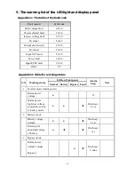
Page 18: ...lt 55 59 Power fault 60 64 Input FUSE fault 65 69 Other 88 Appendix 2 Table for working status S N Working status LED on Front panel Alarm beep Note Normal Battery Bypass Fault 1 Inverter mode mains p...

Page 19: ...ode overload Long beep Warning for battery overload 2 beeps sec Protect operation for battery mode overload Long beep 6 Warning for bypass mode overload One beep 2 sec 7 Fans fault fan icon One beep 2...

Page 20: ...r directly Fault LED on audible buzzer persistently alarm the fault code is 25 39 Inverter voltage fault Please contact the supplier Fault LED on audible buzzer persistently alarm the fault code is 40...

Page 21: ...fail to start when operate On key Pressing time too short Please press the power key more than 2 seconds to start the UPS The input connection is not ready or UPS internal battery disconnect Please co...

Page 22: ...ion The UPS can communicate with PC via analog relay joint and serial interface RS232 The former makes use of the transistor s ON and OFF action to transmit the input power condition and UPS status to...

Page 23: ...otection 8A 12A 15A 20A THDI 6 Bypass voltage range Rated output Voltage 34V Rated output Voltage 32V Bypass Low High restoring point Bypass Low 10V Bypass High 10V Output Output voltage 208VAC 210VAC...

Page 24: ...tput voltage 27 5 0 4V 55 0 6V 55 0 6V 82 5 0 9V Charge method Three stage charging Recharge time 90 capacity after 5hrs charging standard model According to battery capacity long time model Input vol...

Page 25: ...Explanation Foot Explanation 1 empty 6 empty 2 Send 7 empty 3 receive 8 empty 4 empty 9 awaken 5 GND Communication port for PC TCP IP This model UPS can supply one Intelligent Slot at the rear panel w...

Reviews: