8.
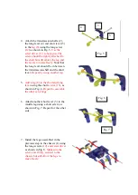
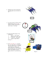
Attach the feet to the legs using the
remaining short screws as shown in
fig. 9.
9.
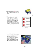
Cover the switch (7) with the cap (5).
Install the battery box (
14
), the
switch (7) and the circuit board (6)
on the chassis. See Fig 10.
10.
Connect the different plugs to the
circuit board:
i.
Battery - socket “BAT”
ii.
Right motor - socket “M1”
iii.
Left motor – socket “M2”
iv.
Switch - socket “SW1”.
See Fig. 11.
11.
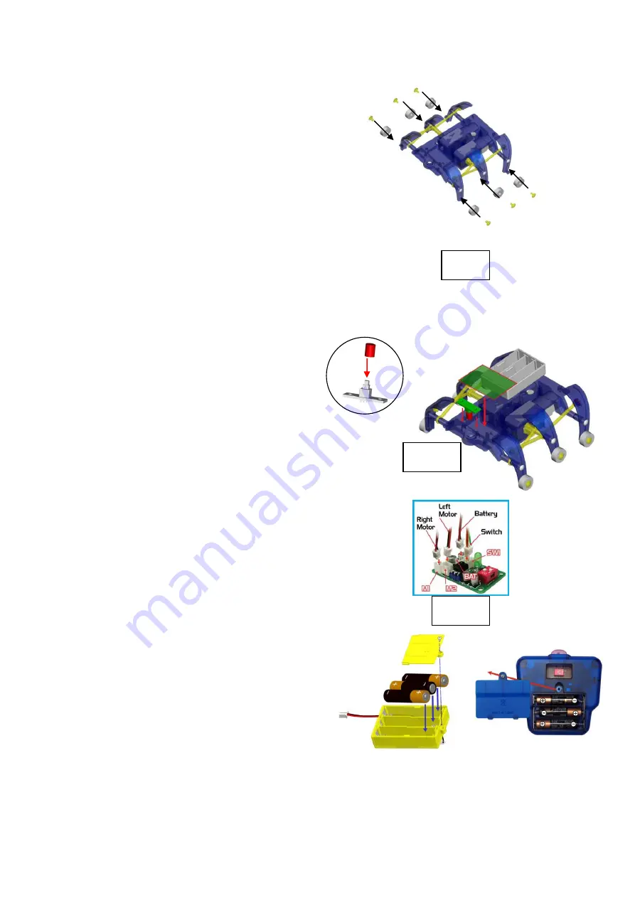
Use
the screwdriver (17)
to loosen
the screw in the battery compartment
door of the battery box (
14
), install 3
AAA batteries according to the
polarity mark. (Fig. 12) Replace the
door and tighten the screw. Similarly,
install 3 AAA batteries into the
remote control (
15
) as shown in Fig.
13.
Fig. 8
Fig. 9
Fig. 10
Fig. 11
Fig. 12
Fig. 13

