Operation 29
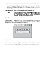
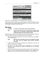
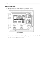
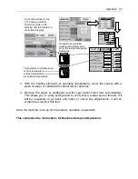
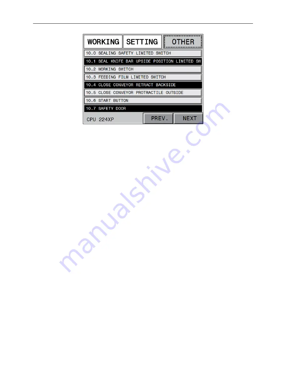
Use the Prev. and Next Buttons to view additional PLC I/O messages.
When an alarm condition exists during running operation, the PLC will display an alarm
pictorial on the screen. Alarm pictorials with explanations of what they mean are listed in
the troubleshooting section of this User Guide.
Film Setup
CAUTION!
Turn off the working switch when setting up the film.
Note:
You can turn the heat on to the sealer heat elements (M.D.
Thermo and T.D. Thermo) to allow them to warm up to
operating temperature while setting up the film.
Select the proper width of center-fold film for the product being packaged, taking into
account the width and height of the package, plus six inches for scrap.
1. Place the film roll on the support rollers of the film unwinder. (See the illustration
on the following page.)
Note:
Place the film center-fold end of the roll toward the infeed
end, away from the operator panel (unless otherwise
specified).
2. Position the film roll on the rollers and tighten the upright bolts on the film rack
collars to hold the film roll in position.
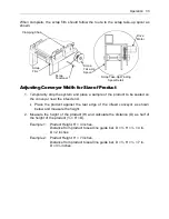
3. Pull down on the film perforator handle approximately 90° to temporarily
disengage the film perforator and hold the film perforator out of the way while
threading the film.
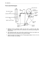
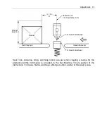
4. Thread the film through and around the idler rollers and the pin perforator as
shown in the Film Unwind Path Diagram Illustration on the following page.
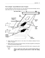
Separate the film so one side of the film is to each side of the film separator.
Summary of Contents for Value VSA2530TK-V1
Page 1: ...VSA Value Series Auto L Sealers User Guide VSA2530TK V1 ...
Page 2: ......
Page 4: ......
Page 73: ...Appendix A Electrical Schematic 73 VSA2530 TKV1 Sheet 2 of 5 ...
Page 74: ...74 Appendix A Electrical Schematic VSA2530 TKV1 Sheet 3 of 5 ...
Page 75: ...Appendix A Electrical Schematic 75 VSA2530 TKV1 Sheet 4 of 5 ...
Page 76: ...76 Appendix A Electrical Schematic VSA2530 TKV1 Sheet 5 of 5 ...
Page 78: ...78 Appendix A Electrical Schematic VSA2530 TKV2 Sheet 2 of 6 ...
Page 79: ...Appendix A Electrical Schematic 79 VSA2530 TKV2 Sheet 3 of 6 ...
Page 80: ...80 Appendix A Electrical Schematic VSA2530 TKV2 Sheet 4 of 6 ...
Page 81: ...Appendix A Electrical Schematic 81 VSA2530 TKV2 Sheet 5 of 6 ...
Page 82: ...82 Appendix A Electrical Schematic VSA2530 TKV2 Sheet 6 of 6 ...
Page 83: ...Appendix B Air Diagram Pneumatic Schematic 83 Appendix B Air Diagram Pneumatic Schematic ...
Page 88: ......


