Operation 35
Setting Conveyor Belt Run and Stop Times
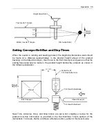
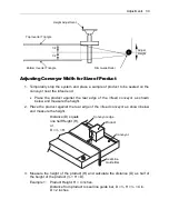
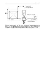
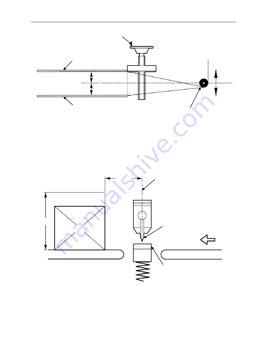
When the sealer is running and sealing product, the beginning transverse seal should
be made at a distance approximately ½ the product height ahead of the product
traveling on the Infeed Conveyor, then move to the Exit Conveyor and pause so that the
ending transverse seal is made ½ the product height behind the product, as shown in
the following illustration..
Seal Time, Advance, Stop, and Skip timers are set when creating a recipe for the
product and this information is provided in the Set Machine Timers section of the
instructions To Create, Name, and Save a Recipe section, earlier in this User Guide.
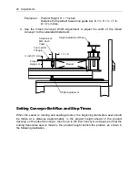
Top Inverter Triangle
Bottom Inverter Triangle
Height Adjustment
Film Guide Roller
1/2
1/2
Adjust
Height
Product
Infeed Conveyor
Exit Conveyor
Centerline of
T.D. Seal/Cutter Arm
½ × H =
D
T.D. Seal/Cutter Seat
T.D. Seal/Cutter Blade
Product
Height, H
Summary of Contents for Value VSA2530TK-V1
Page 1: ...VSA Value Series Auto L Sealers User Guide VSA2530TK V1 ...
Page 2: ......
Page 4: ......
Page 73: ...Appendix A Electrical Schematic 73 VSA2530 TKV1 Sheet 2 of 5 ...
Page 74: ...74 Appendix A Electrical Schematic VSA2530 TKV1 Sheet 3 of 5 ...
Page 75: ...Appendix A Electrical Schematic 75 VSA2530 TKV1 Sheet 4 of 5 ...
Page 76: ...76 Appendix A Electrical Schematic VSA2530 TKV1 Sheet 5 of 5 ...
Page 78: ...78 Appendix A Electrical Schematic VSA2530 TKV2 Sheet 2 of 6 ...
Page 79: ...Appendix A Electrical Schematic 79 VSA2530 TKV2 Sheet 3 of 6 ...
Page 80: ...80 Appendix A Electrical Schematic VSA2530 TKV2 Sheet 4 of 6 ...
Page 81: ...Appendix A Electrical Schematic 81 VSA2530 TKV2 Sheet 5 of 6 ...
Page 82: ...82 Appendix A Electrical Schematic VSA2530 TKV2 Sheet 6 of 6 ...
Page 83: ...Appendix B Air Diagram Pneumatic Schematic 83 Appendix B Air Diagram Pneumatic Schematic ...
Page 88: ......

