Operation 37
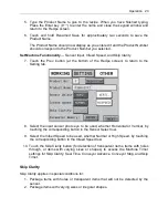
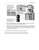
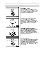
3. With the heating elements at operating temperature, cover the sensor with a
piece of paper or cardboard for about two (2) seconds.
4. Remove the paper or cardboard and the seal function test runs automatically.
This allows you to verify settings and to verify that a proper seal is formed. If it
will be necessary to go back and make or check any adjustments, it will be
evident as a result of this test.
Once the machine is set up for the product, operation is automatic.
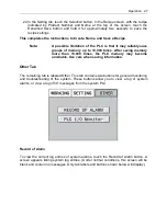
This completes the instructions for Machine Setup and Operation.
OTHER
SETTING
T.D. Thermo:
M.D. Thermo:
0
0
Infeed Width:
0.0
°C
mm
Triangle Height:
0.0
mm
Seal Line Height:
0.0
mm
WORKING
°C
PREV.
SAVE
Set
Set
Set
Set
Set
OTHER
SETTING
Seal Time:
Advance:
0.6
0.6
Conveyor Stop:
0.6
Set
Set
Skip Timer:
0.6
Set
WORKING
Set
Sec.
Sec.
Sec.
Sec.
PREV.
NEXT
T.D.THERMO
M.D.THERMO
PF
PV
SV
PF
PV
SV
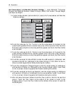
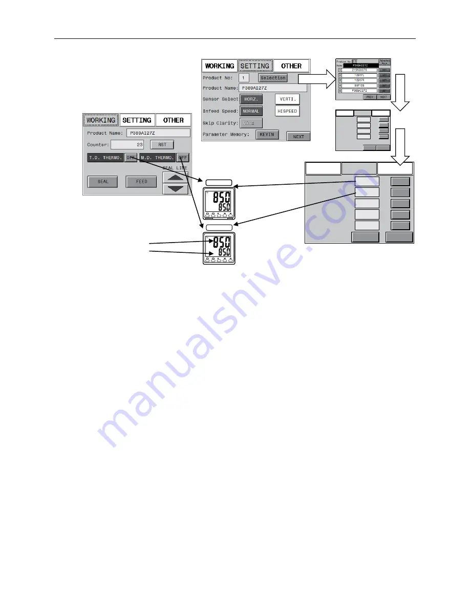
Touch the buttons for the
T.D. Thermo and M.D.
Thermo controls in the
Working Tab to activate the
controllers’ displays.
Temperature controllers show
current temperature
and set temperature
for working temperature.
Temperature controller
working temperatures are
set in the recipe through the
Setting tab.
Summary of Contents for Value VSA2530TK-V1
Page 1: ...VSA Value Series Auto L Sealers User Guide VSA2530TK V1 ...
Page 2: ......
Page 4: ......
Page 73: ...Appendix A Electrical Schematic 73 VSA2530 TKV1 Sheet 2 of 5 ...
Page 74: ...74 Appendix A Electrical Schematic VSA2530 TKV1 Sheet 3 of 5 ...
Page 75: ...Appendix A Electrical Schematic 75 VSA2530 TKV1 Sheet 4 of 5 ...
Page 76: ...76 Appendix A Electrical Schematic VSA2530 TKV1 Sheet 5 of 5 ...
Page 78: ...78 Appendix A Electrical Schematic VSA2530 TKV2 Sheet 2 of 6 ...
Page 79: ...Appendix A Electrical Schematic 79 VSA2530 TKV2 Sheet 3 of 6 ...
Page 80: ...80 Appendix A Electrical Schematic VSA2530 TKV2 Sheet 4 of 6 ...
Page 81: ...Appendix A Electrical Schematic 81 VSA2530 TKV2 Sheet 5 of 6 ...
Page 82: ...82 Appendix A Electrical Schematic VSA2530 TKV2 Sheet 6 of 6 ...
Page 83: ...Appendix B Air Diagram Pneumatic Schematic 83 Appendix B Air Diagram Pneumatic Schematic ...
Page 88: ......

