background image

38   Adjustments 

Adjustments 


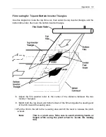
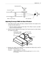
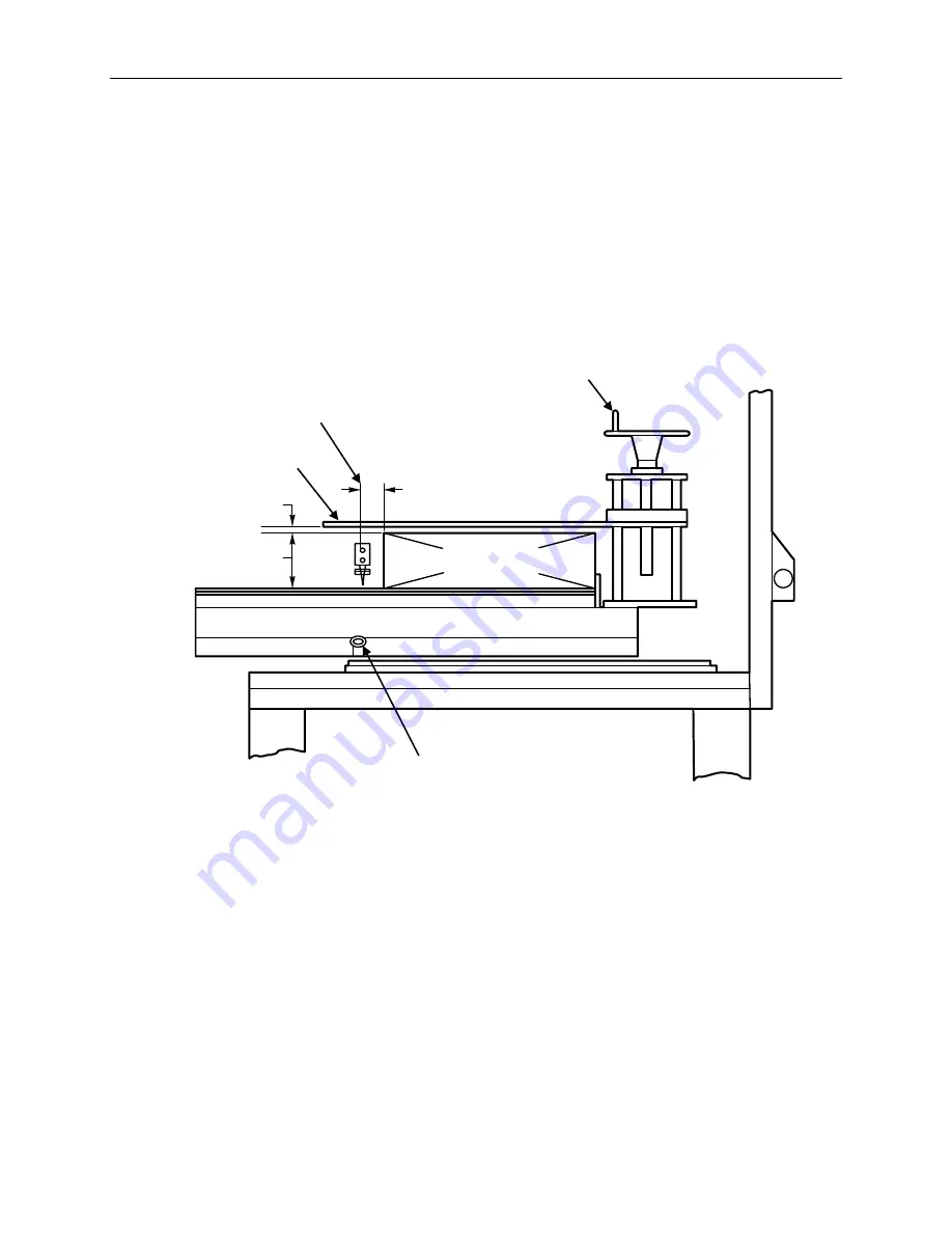
Adjusting the Film Inverter Height and Guide Roller Height 


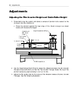
1.  Temporarily stop the system and place a sample of product to be sealed on the 

conveyor near the infeed end. 


  Place  the  product  against  the  rear  edge  of  the  infeed  conveyor  as  shown 

below and measure the height. 


2.  Use the Height Adjustment Wheel to adjust the distance between the two inverter 

triangles  (top and bottom) so that the Top Inverter Triangle  clears the top of  the 
product sample by approximately ½ inch or 13 mm. 


3.  Adjust the film guide roller to the center of the distance between the two Inverter 

Triangles. See the following illustration. 


Height Adjustment Wheel 

Product 

D = ½ × H 

½ inch (13 mm) 

Product 
Height, H 

Width Adjustment 

Top Inverter 
Triangle 

Centerline of 
M.D. Seal/ 
Cutter 

Summary of Contents for Value VSA2530TK-V1

Page 1: ...VSA Value Series Auto L Sealers User Guide VSA2530TK V1 ...

Page 2: ......

Page 3: ...ht and Trademarks Copyright 2017 2022 Engage Technologies All rights reserved All trademarks and brand names are the property of their respective owners Eastey Enterprises 7041 Boone Ave N Brooklyn Park MN 55428 Phone 763 428 4846 Fax 763 795 8867 1 800 835 9344 www eastey com VSA2530TK V1 ...

Page 4: ......

Page 5: ...ustments 38 Adjusting the Film Inverter Height and Guide Roller Height 38 Adjusting Conveyor Width for Size of Product 39 Setting Conveyor Belt Run and Stop Times 40 Maintenance 42 Cleaning 42 Rollers 42 Troubleshooting 43 Alarm Windows 46 Parts List 48 Covers Doors Shutters 48 Scrap Film Guide Rollers Brackets 49 Guide Roller Shafts Leveling Feet Casters 49 Mechanical Ruler 49 Motor Air Connector...

Page 6: ...el Human Interface Display HID Button Switches and Labels 69 Main Power Box with Latch Switch Cooling Fan Transformer Guard 71 Appendix A Electrical Schematics 72 Electrical Schematics VSA2530 TKV1 72 Electrical Schematics VSA2530 TKV2 77 Appendix B Air Diagram 83 Pneumatic Schematic 83 Appendix C Temperature Setting Specifications for Shrink Wrap Plastics 84 Mushroom Insert 84 Warranty Statement ...

Page 7: ...ctrical power before attempting maintenance for any electrical or moving parts Do not place hands head or any part of the body inside the confines of the machine unless the mechanism is securely fastened and the electrical supply is shut off Do not tamper with electrical wiring Use only the specified power supply cable Use only licensed electricians to check or repair electrical wiring In order to...

Page 8: ...erate a machine if any modification has been made This equipment is designed for indoor operation in a typical clean dry factory environment Do not operate the machine in any extremely wet or oily environment that may exceed operating specifications The use of certain types of plastic films in sealing and or shrink wrapping equipment may result in the release of hazardous fumes due to degradation ...

Page 9: ...ng in these zones Pinch hazard Do not place your hands or any object on the moving mechanism Shut down the machine before performing maintenance repair or adjustment Crush hazard Do not place your hands or any object on the moving mechanism Shut down the machine before doing any maintenance repair or adjustment High temperature hazard Do not touch or place hands close to the heating source to avoi...

Page 10: ...hase Weight Weight VSA2530 TKV1 25 in 63 5 cm 30 in 76 cm 71 in 181 cm 69 in 175 cm 95 in 242 cm 220 20 1 1100 lbs 498 kg 1200 lbs 544 kg Sealing Area Main Power On Off Switch Film Roll Infeed Conveyor Outfeed Conveyor Scrap Film Roll Up Area Control Panel Alarm Signal Stack Lights optional Leveling Legs Casters Clamping Chain Inverter Triangle Sealing Area Electrical Panel Perforator Release Leve...

Page 11: ...r Volts Phase Voltage Phase Designator Volts Phase V1 220 1 V5 480 1 Standard features Designed to seal most polyolefin polyethylene and PVC shrink films All aluminum extrusion main frame Normal speed infeed and outfeed conveyors High speed with product indexing Motorized seal height adjustment for various product sizes Seal head equipped with pneumatic air cylinder for automatic sealing Hot knife...

Page 12: ...ining and maintenance VSA2530 maximum film width up to 25 Maximum film roll O D up to 12 80 PSI 220V Single Phase is Standard 480V Single Phase Option is Available Dimensions See Machine Dimensions in Specifications table for overall machine width height and length VSA2530 Height B Takeaway Conveyor Height In Take Conveyor Height Length C Side View Width A End View ...

Page 13: ... be made within ten 10 days of delivery of shipment Unless you do this the carrier will not entertain any claim for loss or damage The agent will make an inspection and grant a concealed damage notation If you give the transportation company a clear receipt for the goods that have been damaged or lost in transit you do so at your own risk and expense All claims must be filled within five 5 months ...

Page 14: ... location is one of the most important considerations for initial setup When selecting the location take into consideration the following factors 1 Adequate power supply nearby 2 Where is the sealer in relation to the power source 3 Where is the sealer in relation to the tunnel and any conveyor s necessary to move the wrapped product Alignment with packaging line 4 Convenience for the operator If ...

Page 15: ...ver smooth flat surfaces If you need to lift the unit to move it you will need to use a pallet jack floor crane or fork lift to move it to its location CAUTION If the L sealer must be lifted for moving use proper equipment when lifting and moving it to ensure it is secure and will not shift When the L sealer has been moved to its location use the levers on the casters to lock the wheels to prevent...

Page 16: ...splays buttons for configuring and controlling the system and obtaining system messages and status information More detail about using the Operator s Panel is explained in the following pages T D Thermo Temperature controller for the L Sealer heat element that is aligned cross wise or transverse to the Machine Direction More specific information about setting the T D temperature controller is prov...

Page 17: ...Use to turn main power to the automatic L sealer on or off CAUTION When the power is turned on be aware of sealer hot surfaces and moving belts and rollers Other Features Film Unwinder The film unwinder is located behind the product infeed conveyor and film separator inverter area behind and to the right of the L sealer enclosure Pin Perforator The pin perforator is inside the film unwinder The Pi...

Page 18: ... Width Adjustment Handle Chain Guard Height Adjustment Rod Intake Conveyor Upper Inverter Triangle Height Adjustment Wheel Vertical Detection Sensor Horizontal Detection Sensor Exit Conveyor Exit Conveyor Base Plate Exit Drive Roller Drive Roller Bearing Guard Plate Adjust ment Screw Exit Rollers Sealer Cutting Arm ...

Page 19: ...Eastey company name touch the screen anywhere within the large rectangle with your finger Note The sensitivity of the screen is such that your finger needs to be in contact with the screen for a fraction of a second longer than just a quick tap If you tap the screen too quickly the touch screen sensor may not sense or respond to it Using the Touch Panel Interface Once you have touched the Eastey s...

Page 20: ...le to manually feed the product and to seal it manually Setting Tab Touch the screen in the Setting tab to view and work with settings The Setting tab allows you to view or set up parameters for products for semi automatic operation Tab areas at top for Other Working and Setting areas of the control Interface A named and saved group of settings or recipe defined and selected for the specific curre...

Page 21: ... the Recipe screen Combined the two pages of the Recipe screen allow you to name define and save up to ten recipes at a time Up to 10 recipes groups of settings each for a different product can be saved at any time Setting tab is selected Touch Selection button to access recipe screens Displays the Product Name the recipe is for Vertical sensor button See notes that follow for when to use Horizont...

Page 22: ...is a Set button Touch the Set button that is in the same Product Number row that you wish to define and name keep your finger in contact for approximately two seconds and the Product No at the top of the screen will display the number for the row you selected If the Recipe has been given a name the name appears in the Name field Enter a Product Name 4 Touch anywhere in the Name field and an on scr...

Page 23: ...eturn to the Setting tab 8 Select the input sensor photo eye to be used whether Horizontal or Vertical by touching the corresponding button in the Sensor Select row 9 Select the Infeed Speed to be used whether Normal or High Speed by touching the corresponding button in the Infeed Speed row 10 Touch the Skip Clarity button for detection of transparent items items with holes through or items with v...

Page 24: ...ed Example 2 Irregular shape package items such as for meats or vegetables etc result from varying shapes and sizes of items and in some cases random orientation of the items they contain These packages present a challenge because the sensor may have difficulty detecting them For these items observe the required timing for the space before and after an item The space between consecutive items must...

Page 25: ... Touch the rectangle for Advance to enter the time in seconds for the film advance timer Acceptable values are 0 0 to 5 0 in tenths of a second increments 13 Touch the rectangle for Conveyor Stop to enter the time in seconds for the conveyor stop timer Acceptable values are 0 1 to 5 0 in tenths of a second increments 14 Touch the rectangle for Skip Timer to enter the time in seconds for the sensor...

Page 26: ...he width setting in millimeters with precision of tenths of a millimeter for the infeed conveyor Touch Enter on the on screen numeric keypad when finished entering the number 19 Touch the rectangle for Triangle Height to enter the height setting in millimeters with precision of tenths of a millimeter for the inverter triangle height Touch Enter on the on screen numeric keypad when finished enterin...

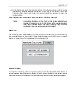
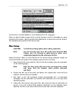
Page 27: ...times After saving memory more than 10 000 times the PLC memory may become unreliable Use care when saving information Other Tab The remaining tab is labeled Other This tab contains two buttons for general monitoring and troubleshooting of the system These buttons allow you to view a log of system alarms or view a log of I O messages from the system PLC Record of Alarm To view the current log entr...

Page 28: ... the Long Message text window when you are finished Touch the Prev button at the bottom of the Record of Alarm screen to return to the previous screen of the Other tab PLC I O Monitor To view messages from PLCs for monitoring I O conditions or for troubleshooting touch the PLC I O Monitor button Scroll up one line Scroll to top See full text of selected message Scroll to bottom Scroll down one lin...

Page 29: ...the width and height of the package plus six inches for scrap 1 Place the film roll on the support rollers of the film unwinder See the illustration on the following page Note Place the film center fold end of the roll toward the infeed end away from the operator panel unless otherwise specified 2 Position the film roll on the rollers and tighten the upright bolts on the film rack collars to hold ...

Page 30: ...the film out about forty inches or one meter and pass the film from the unwinder over the inverter triangles 7 Adjust the height of the Upper Inverter Triangle approximately inch or 13 mm above the height of the package Shrink Film Roll Roller Film Roll Support Roller Perforator Roller Perforator Handle Motorized Roller Film Separator Tension Control Roller Film Position Roller Top Inverter Triang...

Page 31: ...ilm position roller to the center of the distance between the two Inverter Triangles 9 Match both the top sheet and bottom sheet of the film and guide the leading end of the film toward the sealing area 10 Pull the film to the left to the L sealing area and lift the lever to release the pinch wheels Note This is a pinch area Take care to avoid pinching hands or fingers while using the pinch wheel ...

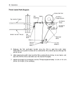
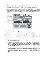
Page 32: ...he following instructions and illustration at the top of the next page to guide the scrap film line around the rollers under the anti slack tensioner and on to the scrap take up spool 1 As scrap begins to be generated guide the scrap film around the roller and guide at the exit end of the L sealer 2 Continue to guide the scrap film around the rollers at the front and under the machine as shown Mos...

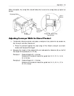
Page 33: ... rear edge of the infeed conveyor as shown below and measure the height 2 Measure the height of the product H and calculate the distance D as half of the height of the product H D Example 1 Product Height H 4 inches Distance from product to seal line guide bar D H 4 in D 2 inches Example 2 Product Height H 7 inches Distance from product to seal line guide bar D H 7 in D 3 inches Clamping Chain Scr...

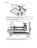
Page 34: ...conveyor to the calculated distance D 5 Adjust the film guide roller to the center of the distance between the two Inverter Triangles See the illustration at the top of the following page H D Distance D equals one half Height H or D H Product Conveyor Conveyor edge Seal Line Guide Bar Height Adjustment Wheel Product D H inch 13 mm Product Height H Width Adjustment Top Inverter Triangle Centerline ...

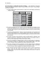
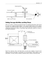
Page 35: ...eight behind the product as shown in the following illustration Seal Time Advance Stop and Skip timers are set when creating a recipe for the product and this information is provided in the Set Machine Timers section of the instructions To Create Name and Save a Recipe section earlier in this User Guide Top Inverter Triangle Bottom Inverter Triangle Height Adjustment Film Guide Roller 1 2 1 2 Adju...

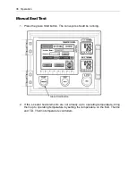
Page 36: ...button The conveyors should be running 2 If the L sealer heat elements are not already up to operating temperature bring them up to operating temperature by setting the temperature on the M D Thermo and T D Thermo temperature controllers Green Start Button ...

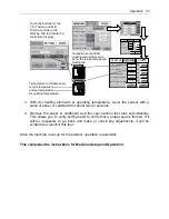
Page 37: ...c This completes the instructions for Machine Setup and Operation OTHER SETTING T D Thermo M D Thermo 0 0 Infeed Width 0 0 C mm Triangle Height 0 0 mm Seal Line Height 0 0 mm WORKING C PREV SAVE Set Set Set Set Set OTHER SETTING Seal Time Advance 0 6 0 6 Conveyor Stop 0 6 Set Set Skip Timer 0 6 Set WORKING Set Sec Sec Sec Sec PREV NEXT T D THERMO M D THERMO PF PV SV PF PV SV Touch the buttons for ...

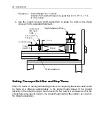
Page 38: ...ure the height 2 Use the Height Adjustment Wheel to adjust the distance between the two inverter triangles top and bottom so that the Top Inverter Triangle clears the top of the product sample by approximately inch or 13 mm 3 Adjust the film guide roller to the center of the distance between the two Inverter Triangles See the following illustration Height Adjustment Wheel Product D H inch 13 mm Pr...

Page 39: ...gainst the rear edge of the infeed conveyor as shown below and measure the height 3 Measure the height of the product H and calculate the distance D as half of the height of the product H D Example 1 Product Height H 4 inches Distance from product to seal line guide bar D H 4 in D 2 inches H D Distance D equals one half Height H or D H Product Conveyor Conveyor edge Seal Line Guide Bar Top Inverte...

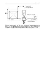
Page 40: ...he sealer is running and sealing product the beginning transverse seal should be made at a distance approximately the product height ahead of the product traveling on the Infeed Conveyor then move to the Exit Conveyor and pause so that the ending transverse seal is made the product height behind the product as shown in the following illustration Height Adjustment Wheel Product D H inch 13 mm Produ...

Page 41: ...oduct and this information is provided in the Set Machine Timers section of the instructions To Create Name and Save a Recipe section earlier in this User Guide Product Infeed Conveyor Exit Conveyor Centerline of T D Seal Cutter Arm H D T D Seal Cutter Seat T D Seal Cutter Blade Product Height H ...

Page 42: ...etergent in small amounts DO NOT splash water or other liquids on or into the machine DO NOT hose clean the machine with water 3 The machine has been coated with an anti corrosion finish Avoid contact with liquid acid or gas or other corrosives 4 After cleaning the machine lubricate any moving parts as required 5 Check the air filter and regulator daily If water has accumulated empty the water Rol...

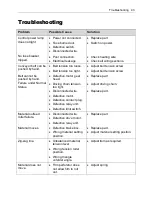
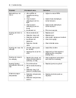
Page 43: ...d Failure under Normal Status Defective motor gear head Driving chain tension too tight Disconnected wire Defective motor Defective contact plug Defective relay unit Defective limit switch Replace part Adjust driving chain Replace part Material outfeed roller failure Disconnected wire Defective drive motor Defective relay unit Replace part Material moves Defective brake box Wrong material setting ...

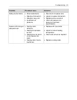
Page 44: ...lace part Check part replace as needed Check air supply Check throttle valve Sealing arm rises too abruptly Throttle valve opens too quickly Sealing time is set too short Adjust flow control Adjust time of limit switch in safety device to lengthen sealing time Sealing arm lowers too abruptly Electronic sensors not aligned horizontally or vertically or dirty Check alignment and adjust and clean as ...

Page 45: ... or replace limit switch Replace part as required Check air pressure Air pressure must meet specifications Sealer not forming an adequate seal Sealing cutter defective Heating temperature too low Sealing time too short or air pressure too weak Sealing cutter heat is insufficient Replace with new cutter Adjust to correct heating temperature Check and correct as required Replace sealing cutter ...

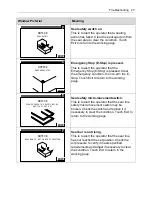
Page 46: ...ator that the seal line has reached the lowest limit Raise the seal line to clear the condition Touch Exit to return to the working page Seal at highest limit This is to alert the operator that the seal line has reached the highest limit Lower the seal line to clear the condition Touch Exit to return to the working page Safety door open A safety door is open Find the safety door that is open and c...

Page 47: ...fety micro movement switch This is to alert the operator that the seal line safety micro movement switch may be broken Check the switch and replace it if necessary to clear the condition Touch Exit to return to the working page Seal bar is not rising This is to alert the operator that the seal line has not reached the set position Check the air pressure to verify it meets specified requirements an...

Page 48: ...rance Left and Right 1 each LSA706A AC04 2 A4 5HMLSA706AXA4 Right Acrylic Cover LSA706A AC05 1 A5 5HMLSA706AXA4 Left Acrylic Cover LSA706A AC06 1 A6 5HMLSA706AXA4 Control Panel Frame LSA706A AC07 1 A7 Left and Right Shutters LSA706A AP01 1 A8 Rear Cover LSA706A AP02 1 A9 Under Cover Plate LSA706A AP03 1 A10 Right Shutter LSA706A AP07 1 A1 A2 A3 A3 A4 A5 A6 C1 C2 A7 A8 A9 A10 1 F1 F1 F1 F1 C3 C3 C3...

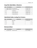
Page 49: ...ide Wheel LSA706A CM05 4 C4 Collector Guide Seat LSA706A CP05 1 C5 Collector Guide Seat LSA706A CP06 2 C6 Collector Guide Seat LSA706A CP03 1 Guide Roller Shafts Leveling Feet Casters ITEM PART NUMBER DESCRIPTION SPECIFICATION Q TY F1 Idler Shaft LSA706A FM09 4 F2 Wheel 6 F3 Tripod 6 F4 Handle 2 Mechanical Ruler ITEM PART NUMBER DESCRIPTION SPECIFICATION Q TY 1 5EL0406013600 Mechanical Ruler 0 8TX...

Page 50: ...1 5 5CB615GE12 5KBF Gearbox 5GE12 5KBF 1 6 5AB04HP7T11S Photoelectric Switch HP7 T11 1 7 5AE05TRT244ROGW Warning Light TPTL5 74 4 24V 1 8 5BE010608ZZ Bearings 608ZZ KSK 4 9 5BF011B3X13T15 M65 Sprockets RS35 13T D 15 M6 2 5X2 5 1 10 5AB17QKS8 Safety Switch QKS 8 AC400V2A 4 11 5DB13BFR300H Pressure Regulator BFR 300S 1 12 5DC02SPC1203 Quick Connector PC12 03T PISCO 1 A1 A3 A4 A5 A5 A6 A6 B1 B2 B2 D1...

Page 51: ...N SPECIFICATION Q TY D1 Motor Cover LSA706A DP01 1 D2 Outfeed Motor Seat LSA706A DP03 1 D3 Outfeed Rack LSA706A DP04 2 Infeed Slide Electric Eye ITEM PART NUMBER DESCRIPTION SPECIFICATION Q TY B1 Guide Rod LSA706A BP11 1 B2 Electric Eye Seat LSA706A BP17 2 B3 Input Section Slide LSA706A BP15 2 Safety Switch Seats Roller Conveyor Parts ITEM PART NUMBER DESCRIPTION SPECIFICATION Q TY A1 5HMLSA706AXA...

Page 52: ...0 RUU 2 4 5BE03UFL002 Bearing Units UFL002 M4 JWT 2 9 5BA0113X048 Roller Chain RS35 48 1 11 5CB025RK90GECW2ML2 Reversible Motor 5RK90GE CW2ML2 1 12 5CB615GE12 5KBF Gearbox 5GE12 5KBF 1 14 5AB13HY57B0213 Red E Stop Button Switch Box FCH HY57B 02 1 3 1 15 5BF011B3X13T15 M65 Sprockets RS35 13T D 15 M6 2 5X2 5 2 19 5AB17QKS8 Pickup Belt QKS 8 AC400V2A 1 B1 B2 B3 B5 B5 B6 B6 B13 B14 B17 B18 B19 B24 B25...

Page 53: ...30X15LSA 706A1 BC01 2 B2 Left Side Panel LSA706A BM01 1 B3 Right Side Panel LSA706A BM02 1 B5 Tension Rod Axis LSA706A BM05 2 B6 Tension Rod Roller LSA706A BM06 1 B13 Transmission Roller LSA706A BM13 1 B14 Axis LSA706A BM14 1 B17 Shutter LSA706A BP03 1 B18 Motor Cover LSA706A BP04 1 B19 Shield LSA706A BP05 1 B24 Motor Seat LSA706A BP10 1 B25 Cover Plate LSA706A BP12 1 ...

Page 54: ...RK15GN CW2L2 1 5 5CB613GN18KF Gearbox 3GN18KF 1 6 5AB05IM1204NNSZW1 Proximity Switch IM12 04NNS ZW1 2 7 5BB036X428 Round Belt 6 Ø X428LLSA504 605 C 1 8 5EH1005 Stainless Steel Tube Bundle 5 1 ITEM PART NUMBER DESCRIPTION SPECIFICATION Q TY A1 Line Box LSA706 AP04 1 ITEM PART NUMBER DESCRIPTION SPECIFICATION Q TY C1 5FDLSA706A1CC01 Inner Containment Disc 4 5TX350LSA706A1 CC01 1 C1 C2 C3 C4 C5 C6 C7...

Page 55: ... Passive Wheel LSA706A CM02 1 C5 Spool Axle Rod LSA706A CM03 1 C6 Coil Holder LSA706A CM04 2 C7 Scrap Disk Holder LSA706A CM06 1 C8 Scrap Disk Retention Pawl LSA706A CM07 1 C9 Tension Roller Axis LSA706A CM08 1 C10 Material Tension Roller LSA706A CM09 1 C11 1 Coil Holder LSA706A CP01 1 C12 Scrap Winding Claw LSA706A CP02 1 C13 Roll Waste Guide Rod LSA706A CP04 1 ...

Page 56: ... JWT 2 5 5BF011B3X13T15M65 Sprockets RS35 13T D 15 M6 2 Hole groove 5X2 5 1 6 5BA0113X037 Roller Chain RS35 37 1 7 5BB01SL01X600X2010 Pick Up Belt Out SL 4DU G ENS 600X2010 LSA 706A 1 ITEM PART NUMBER DESCRIPTION SPECIFICATION Q TY B1 5HFQLSA706ABC01 Output Entry Zone Master Axis 54X734X630X15LSA706A1 BC01 1 ITEM PART NUMBER DESCRIPTION SPECIFICATION Q TY D1 Conveyor Belt Seat LSA706A DM01 2 D2 Ro...

Page 57: ...t 57 ITEM PART NUMBER DESCRIPTION SPECIFICATION Q TY D5 Transmission Roller LSA706A DM05 1 D6 Conveyor Belt Support LSA706A DM06 2 D7 Link LSA706A DM07 1 D8 Guides LSA706A DP02 1 D9 Output Holder LSA706A DP05 2 ...

Page 58: ...gs 6904ZZ ISK 4 2 5BE03UFL004 Bearing Units UFL004 JWT 4 3 5DA01ALXFA80X200 Pneumatic Cylinder AL FA 80 ØX200ST M 1 4 5BE07CJM20X1 5 Floating Joint CJ M20X1 5 1 5 5CF08TM03TATS06X25 0 Screw Lifts TM 3T A T S 1 6 250 4 6 5CB015IK90GECW2TE Induction Motor 5IK90GE CW2TE 1 7 5CB615GE12 5KBF Gearbox 5GE12 5KBF 1 ...

Page 59: ...M PART NUMBER DESCRIPTION SPECIFICATION Q TY D1 Nylon Fixed Plate LSA706A DP06 1 ITEM PART NUMBER DESCRIPTION SPECIFICATION Q TY E1 Shaft Sleeve LSA706A EM01 2 E2 Axis LSA706A EM02 1 E3 Spur Gear Holder LSA706A EM04 4 E4 Rack LSA706A EM05 8 E5 Spur Gears LSA706A EM06 4 E6 Main Floor LSA706A EP03 1 E7 Pneumatic Cylinder Fixed Plate LSA706A EP07 1 E8 Upper Cover LSA706A EP08 2 E9 Side Panels 1 LSA70...

Page 60: ...60 Parts List ITEM PART NUMBER DESCRIPTION SPECIFICATION Q TY F5 Loaded Material Wheel Seat LSA706A FM12 1 F6 Clamping Wheel Base LSA706A FM13 2 F7 Clip Material Wheel Axis Under LSA706A FM16 1 ...

Page 61: ...Cartridge Heaters 9 5 Ø X 670M MX220VX0 7KW 1 6 5AF049 50770X210 Cartridge Heaters 9 5 Ø X 770M MX220VX1 0KW 1 7 5DB014V31010X1X2 4D Solenoid Valve 4V310 10 DC24V NVA 7521 D2 1 8 5DB36PS02 Plastic Muffler PS 02 1 4PT 2 9 5EH1428X14X30X6N Compression Spring Nickel 2 8TX14X30X6N 6 E1 E1 E2 E2 E3 E3 E4 E4 E4 E5 E6 E7 E8 E9 E10 E11 E12 E13 E14 2 E14 1 E15 1 E15 2 E16 E17 E18 E18 E19 E19 E20 E21 1 E21 ...

Page 62: ...late LSA706A EM10 1 E6 Horizontal Sealing Knife LSA706A EM11 1 E7 Vertical Seal Upper Plate LSA706A EM12 1 E8 Vertical Sealing Knife LSA706A EM13 1 E9 Upper Sealing Arm LSA706A EP01 1 E10 Lower Sealing Arm LSA706A EP02 1 E11 Lifting Plate LSA706A EP04 1 E12 Medial Plate 1 LSA706A EP05 1 E13 Medial Plate 2 LSA706A EP06 1 E14 1 Longitudinal Inside Outside Lamination Plate LSA706A EP10 1 1 E14 2 Long...

Page 63: ...ist 63 ITEM PART NUMBER DESCRIPTION SPECIFICATION Q TY E21 1 Left and Right Contacts LSA706A EP17 1 2 E21 2 Left and Right Contacts LSA706A EP17 2 2 E22 Micro Fixed Seat LSA706A EP19 1 E23 Bolt LSA706A EP22 10 ...

Page 64: ...7N 2 3 Reversible Motor 5RK60GE CW2ML2 1 4 Gearbox 5GE12 5KBF 1 5 Sprockets RS35 11T D 15 M6 2 Hole Groove 5X2 5 1 6 Sprockets RS35 13T D 15 M6 2 Hole Groove 5X2 5 1 7 Sprockets RS35 20T D 15 M6 2 Hole Groove 5X2 5 1 8 Roller Chain RS35 139 Eye 1 9 Roller Chain RS35 125 Eye 1 10 Roller Chain RS35 75 Eye 1 F1 F2 F3 F4 F5 F6 F7 F8 F9 F10 F11 F12 F13 F14 1 2 3 4 5 6 7 8 9 10 ...

Page 65: ... Seat LSA706A FM04 2 F5 Support Pole LSA706A FM05 2 F6 Axis of Folded Material LSA706A FM06 1 F7 Upper Fixed Plate LSA706A FM07 1 F8 Lower Fixed Plate LSA706A FM08 1 F9 Bearing Collar LSA706A FM10 1 F10 Tailing Device C LSA706A FM14 1 F11 Tailing Device B LSA706A FM15 1 F12 Clip Holder LSA706A FP01 1 F13 Motor Mounting Plate LSA706A FM02 1 F14 Tailing Device A LSA706A FM04 1 ...

Page 66: ... 5BE03UFL001 Bearing Units UFL001 JWT 6 5 5BE03UFL002 Bearing Units UFL002 M4 JWT 2 6 5BE016800ZZ Bearings 6800ZZ ISK 2 7 5AB06Z15GQ22B Micro Switch Z 15GQ22 B 1 8 5AC15CB2 Microswitch Protective Cover KSS CB 2 1 9 5BC07BR75R Crank Handle BS75R D 10 Ø M6X2 1 10 5EH1416X9X30X8N Compression Spring Nickel 1 6TX9X30X8N 1 11 5BA0113X066 Roller Chain RS35 66 1 12 5BE06SFPJ20 Self Lubricating Bearings SF...

Page 67: ...TY G1 5HFQLSA807AGC01 Pull film drive shaft 50 Ø X1010X912X15 LSA706AGC01 1 G2 Support Pole LSA706A GM01 3 G3 Support Pole LSA706A GM02 1 G4 Film Material Positioning Rod LSA706A GM03 2 G5 Rear Material Roller LSA706A GM05 2 G6 Rear Material Roller Axis LSA706A GM06 2 G7 Counterweight LSA706A GM07 1 G8 Counterweight Fixed Rod LSA706A GM08 1 G9 Eccentric Wheel LSA706A GM09 1 G10 Eccentric Wheel 1 L...

Page 68: ...Shutter LSA706A GP03 1 G25 Right Shutter LSA706A GP04 1 G26 Tension Adjustment Plate LSA706A GP05 2 G27 Linkage for Rod Holder LSA706A GP06 2 G28 Linkage for Lever Stopper LSA706A GP07 2 G29 Blown Film Separation Board LSA706A GP088 1 G30 Fixed Pedestal 1 LSA706A GP099 1 G31 Fixed Pedestal 2 LSA706A GP10 1 ...

Page 69: ...d 1 4 5AB33SHAF2212B2R Chain Button Switch FHD NPB22 R02 2B220V arrow 1 5 5AA01E5CCRX2DSM802 Temperature Controller E5CC RX2DSM 802 AC DC24 1 6 5FD0133X25X45 Acrylic Signs NP 22 2TX35X45 START 2 7 5FD0132X25X45 Acrylic Signs NP 22 2TX45 STOP 1 8 5FD0106X40X12 Acrylic Signs 2TX40X12 E STOP 1 9 5FD0160X40X12 Acrylic Signs 2TX40X12 M D THERMO 1 10 5FD0161X40X12 Acrylic Signs 2TX40X12 M D THERMO 1 11 ...

Page 70: ...70 Parts List ITEM PART NUMBER DESCRIPTION SPECIFICATION Q TY H2 Human Interface Distribution Box LSA706A HP05 1 H3 Control Box Cover LSA706A HP07 1 ...

Page 71: ...AG1312X12X2 Cooling Fan with Net 12XCN 220V ACIUF120B2 FG120 1 4 5BC4514104 Door Hinge 14104 2 5 5AA18TBY302 Buzzer TBY 302 220V 1 ITEM PART NUMBER DESCRIPTION SPECIFICATION Q TY H1 Transformer Guard LSA706A HC01 1 H2 Distribution Box Door LSA706A HP01 1 H3 Distribution Box LSA706A HP02 1 H4 Switchboard LSA706A HP03 1 H5 Distribution Box Fixed Seat LSA706A HP06 2 H6 Transformer Base LSA706A HP08 1...

Page 72: ...72 Appendix A Electrical Schematic Appendix A Electrical Schematics Electrical Schematics VSA2530 TKV1 ...

Page 73: ...Appendix A Electrical Schematic 73 VSA2530 TKV1 Sheet 2 of 5 ...

Page 74: ...74 Appendix A Electrical Schematic VSA2530 TKV1 Sheet 3 of 5 ...

Page 75: ...Appendix A Electrical Schematic 75 VSA2530 TKV1 Sheet 4 of 5 ...

Page 76: ...76 Appendix A Electrical Schematic VSA2530 TKV1 Sheet 5 of 5 ...

Page 77: ...Appendix A Electrical Schematic 77 Electrical Schematics VSA2530 TKV2 VSA2530 TKV2 Sheet 1 of 6 ...

Page 78: ...78 Appendix A Electrical Schematic VSA2530 TKV2 Sheet 2 of 6 ...

Page 79: ...Appendix A Electrical Schematic 79 VSA2530 TKV2 Sheet 3 of 6 ...

Page 80: ...80 Appendix A Electrical Schematic VSA2530 TKV2 Sheet 4 of 6 ...

Page 81: ...Appendix A Electrical Schematic 81 VSA2530 TKV2 Sheet 5 of 6 ...

Page 82: ...82 Appendix A Electrical Schematic VSA2530 TKV2 Sheet 6 of 6 ...

Page 83: ...Appendix B Air Diagram Pneumatic Schematic 83 Appendix B Air Diagram Pneumatic Schematic ...

Page 84: ... Vinyl Chloride Temperature settings Pad type Dwell Time 325 F front bar 325 F side bar Felt Approximately 1 second Polyolefin Temperature settings Pad type Dwell Time 335 F front bar 335 F side bar Sponge rubber Approximately 1 second Polyethylene Temperature settings Pad type Dwell Time 360 F front bar 360 F side bar Sponge rubber Approximately 1 5 second ...

Page 85: ...ubject to normal wear tear and replacement which are warranted to be free from defects in material and workmanship Sealing Quality Sealing quality achieved in a given application is dependent on the installation the material handling and the maintenance provided Eastey makes no warranty that the sealing quality achieved in an application will be the same as that achieved on a test piece in our dem...

Page 86: ...y to the original buyer Limited Warranty THE ABOVE WARRANTY IS EXCLUSIVE AND IN LIEU OF ALL OTHER WARRANTIES WHETHER EXPRESSED OR IMPLIED INCLUDING THE IMPLIED WARRANTIES OF MERCHANTABILITY FITNESS FOR A PARTICULAR PURPOSE AND NONINFRINGEMENT Disclaimer of Damages REGARDLESS OF WHETHER ANY REMEDY SET FORTH HEREIN FAILS OF ITS ESSENTIAL PURPOSE IN NO EVENT WILL EASTEY BE LIABLE FOR ANY SPECIAL CONS...

Page 87: ...lue Series L Sealer please contact Eastey Technical Service at one of the numbers listed below Toll Free Phone 800 835 9344 Phone 763 428 4846 Fax 763 795 8867 E mail info eastey com Web www eastey com Thank you again for your purchase of Eastey products We are pleased to be a part of your packaging needs ...

Page 88: ......
Reviews: