8B7489 – 01MAY97
7
Connecting the New DRYER THERMISTOR
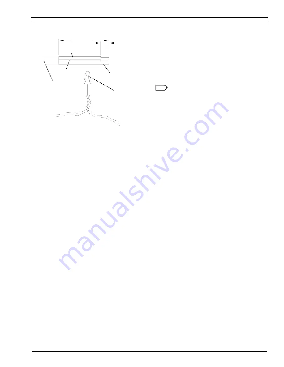
[1] Prepare the wires for the new DRYER
THERMISTOR. See Step 1 on Page 5.
[2] Twist together each pair of wires, insert into a
CLOSED-END SPLICE, and close the SPLICE:
• 2 red wires
• 2 black wires
• 2 bare ground wires
Note
The bare ground wires do not need insulation.
[3] Move the wires to positions that will not have
contact with moving parts or be compressed by
the DRYER BLOWER.
[4] Install the DRYER BLOWER in the
PROCESSOR.
[5] Check that the BLOWER SLEEVE is in the
correct position, and no leakage of air occurs.
4 cm
(1 1/2 in.)
5 mm
(1/4 in.)
H104_0596AA
SPLICE
CLOSED-END
CASING
OUTER
red wire
black wire
bare wire
H104_0596ACA
Summary of Contents for 3059
Page 2: ......
Page 3: ......
Page 4: ......
Page 5: ......
Page 6: ......
Page 7: ......
Page 8: ......
Page 9: ......
Page 10: ......
Page 11: ......
Page 12: ......
Page 13: ......
Page 14: ......
Page 15: ......
Page 16: ......
Page 17: ......
Page 18: ......
Page 19: ......
Page 20: ......
Page 21: ......
Page 22: ......
Page 23: ......
Page 24: ......
Page 25: ......
Page 26: ......
Page 27: ......
Page 28: ......
Page 29: ......
Page 30: ......
Page 31: ......
Page 32: ......
Page 33: ......
Page 34: ......
Page 35: ......
Page 36: ......
Page 37: ......
Page 38: ......
Page 39: ......
Page 40: ......
Page 41: ......
Page 42: ......
Page 43: ......
Page 69: ...MODIFICATION INSTRUCTIONS TYPE1 10 29JUN96 8B6658 ...


