8B7489 – 01MAY97
11
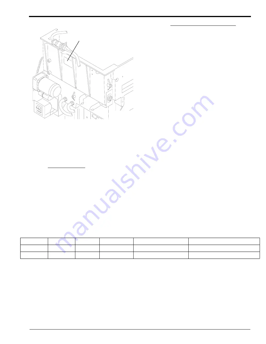
Figure 4
180 LP or 180 LPS PROCESSORS
[3] For the 180 LP or 180 LPS PROCESSOR only:
(a) Remove the DRIVE SIDE PANEL.
(b) Circle the “8” on the MODIFICATION
LABEL. Use permanent ink.
Circle the “8” on 180 LP and
180 LPS PROCESSORS.
(c) Install:
• DRYER RACK
• TOP EXIT RACK
• WET SECTION COVER
[4] For all PROCESSORS:
(a) Install the PANELS.
(b) Close the TOP COVER, or move the PROCESSOR into the MULTILOADER.
(c) Move the main wall CIRCUIT BREAKER to “ON”.
(d) Energize the PROCESSOR.
(e) Check for correct operation of the PROCESSOR.
Publication History
Print Date
Pub. No.
ECO No.
Affected Pages
File Name
Notes
SEP96
8B7489
2619-143
All
ma3058_35_01sep96.doc
New Modification Instructions.
01MAY97
8B7489
2619-143
All
ma3058_35_01may97.doc Revision.
H127_0218AA
H127_0218ACA
MODIFICATION LABEL
Summary of Contents for 3059
Page 2: ......
Page 3: ......
Page 4: ......
Page 5: ......
Page 6: ......
Page 7: ......
Page 8: ......
Page 9: ......
Page 10: ......
Page 11: ......
Page 12: ......
Page 13: ......
Page 14: ......
Page 15: ......
Page 16: ......
Page 17: ......
Page 18: ......
Page 19: ......
Page 20: ......
Page 21: ......
Page 22: ......
Page 23: ......
Page 24: ......
Page 25: ......
Page 26: ......
Page 27: ......
Page 28: ......
Page 29: ......
Page 30: ......
Page 31: ......
Page 32: ......
Page 33: ......
Page 34: ......
Page 35: ......
Page 36: ......
Page 37: ......
Page 38: ......
Page 39: ......
Page 40: ......
Page 41: ......
Page 42: ......
Page 43: ......
Page 69: ...MODIFICATION INSTRUCTIONS TYPE1 10 29JUN96 8B6658 ...


