


4
Eastwood Technical Assistance: 800.544.5118 >> techelp@eastwood.com
To order parts and supplies: 800.345.1178 >> eastwood.com
5
TURBINE GUN SET-UP
Remove all components from carton, identify them and become familiar with their purpose.
PLEASE READ INSTRUCTIONS CAREFULLY.
NEEDLE/NOZZLE SELECTION
It is important to remember that the highly effi cient design of this turbine painting system
delivers a much higher volume of air to the Turbine paint gun than a conventional compressed air
paint gun. As result, the required Needle/Nozzle sizes for the Turbine gun will be much smaller
than those of a conventional, compressed air paint gun when spraying the same material. The
Eastwood Turbine Gun is assembled with a 0.8mm Needle/Nozzle set and Air Cap as standard.
All others denoted by *(1.0mm, 1.3mm, 1.5mm & 1.8mm) are available separately.
Use the following chart as a guide for selecting the correct Needle/Nozzle & Air Cap sizes:
COATING
NEEDLE/NOZZLE SIZE
Primers
1.5mm*
Primer Sealers
1.3mm* or 1.5mm*
Epoxy Primers
1.8mm*
Solvent Based & Urethane Basecoats
0.8mm, 1.0mm*, 1.3mm*
Fine Metallics & Pearls
0.8mm, 1.0mm*
Waterbourne-Basecoats
0.8mm, 1.0mm*
Enviro-Base
0.8mm,1.0mm*,1.3mm*
Clearcoats/Low Solid
0.8mm,1.0mm*,1.3mm*
Clearcoats/Med/High Solids
1.0mm*, 1.3mm*
Single Stage Urethane
1.5mm*
*Available Separately
PAINT CUP SET-UP
• For most coatings using the standard, as supplied 0.8mm or optional 1.0mm or 1.3mm
nozzle, the Turbine Paint Gun may be used as confi gured.
• If using thicker coatings requiring the use of the optional 1.5mm or 1.8mm Needle/Nozzle
sets or if additional Turbine Gun performance is desired, install the optional Air Feed
Connector system.
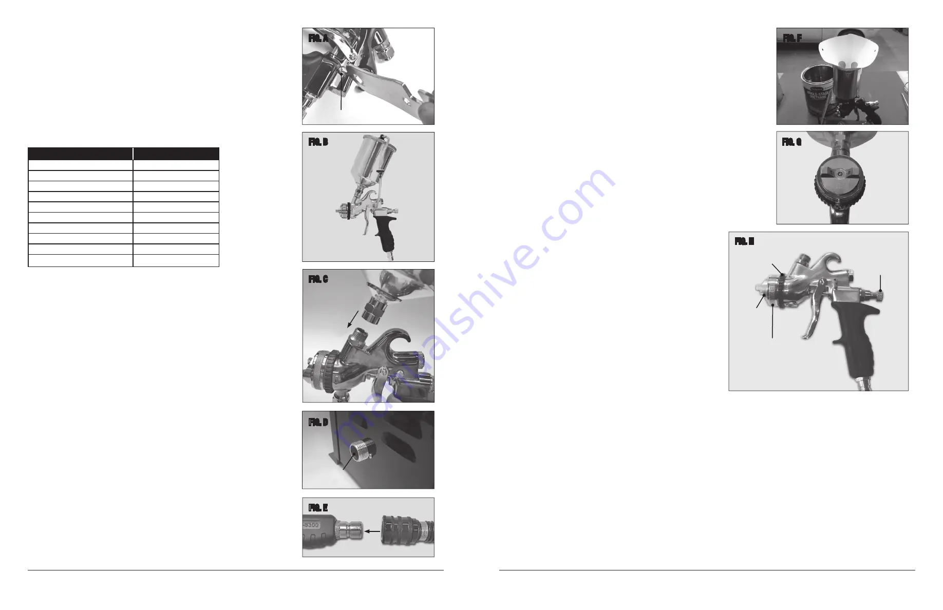
To install:
- Remove the Stainless Steel Screw located on the left side of the Gun Body and
replace it with the barbed air fi tting
(Fig A)
.
- Select the Paint Gun Lid with the barbed air fi tting.
- Slip the Clear Plastic Hose onto both barbed air fi ttings making sure the black half
of the check valve is directed toward the paint gun cup
(Fig B)
.
• Attach Paint Cup by threading onto the male paint inlet fi tting at the top of the gun
(Fig C)
.
NOTE:
Several popular disposable paint cup adapter systems fi tting the common M16x 1.5
thread will work well on this gun.
TURBINE & HOSE SET-UP
• Attach the Air Supply Hose to the Turbine Unit:
- Thread the female fi tting on the end of the Air Supply Hose onto the male fi tting of
the lower left side of the Turbine Unit
(Fig D)
.
- Hand-tighten securely.
• Connect opposite end of Air Supply Hose to Paint Gun:
- Pull back on the spring-loaded ring of the larger female quick-disconnect fi tting.
- Slip in the, smaller male quick-disconnect fi tting in the bottom of the Paint Gun.
- Release ring
(Fig E)
. The gun should be connected to hose. Pull gently to test.
NOTE
: an identical fi tting is attached to the top of the Turbine Unit for gun storage.
FIG. A
FIG. B
FIG. C
FIG. D
FIG. E
Turbine Connection
Blanking Screw
PREPARATION
• The HVLP Paint Gun is assembled with a 0.8mm Needle/Nozzle set which will
accommodate a wide range of coating viscosities.
• Follow label instructions and thoroughly mix the paint or coating material, thinning or
reducing may be necessary. Follow coating manufacturer’s instructions for thinning.
• The use of a Paint Strainer when fi lling cup is strongly recommended to avoid possible
Needle/Nozzle blockage
(Fig F).
GUN SETTINGS
•
Fan Pattern Orientation
- Make sure the Air Cap is properly oriented to produce a vertical
fan spray pattern by viewing the HVLP Paint Gun from the front.
(Fig G)
. Note: This is the
most common setting. To adjust to a horizontal pattern, rotate Retaining Ring by rotating
counter-clockwise slightly, adjust Air Cap then re-tighten Retaining Ring.
•
Fan Pattern Size & Shape
– For larger Fan Pattern, Adjust Retaining Ring toward the “ + ”
by rotating downward. To reduce Fan Pattern, Adjust Retaining Ring toward the “ - ” by
rotating downward
(Fig H).
NOTE:
fully rotating toward the “ - ” will produce a round, focused spray pattern.
•
Fluid Control Setting
– The Fluid Control regulates the distance the Needle travels and the
amount of paint or coating fl owing through the gun. Note: While a wider opening is generally
desired, a fi ne adjustment must always be made due to many variables including; paint
viscosity and composition, air temperature and ambient humidity, barometric
pressure and more. To adjust, rotate the Fluid Control Knob outward (counter-
clockwise as viewed from the rear) to increase fl ow and turn inward to reduce
fl ow
(Fig H)
.
IMPORTANT NOTE BEFORE PAINTING:
It is always best to test spray on sheets
of cardboard or masking paper with the actual coating you will be applying while
making your adjustments to become familiar with the gun and achieve the ideal
Fluid Control Setting. A small amount of product wasted at this point can avoid great
disappointment in your results and the need to re-do your work later.
OPERATION
• Place a small amount of mild solvent compatible with the coating about to be
used in the Paint Cup then run it through the HVLP Paint Gun to remove any
residual manufacturing oils or lubricants present in the Paint Gun or Cup.
• Plug power cord into suitable electrical source.
IMPORTANT NOTE BEFORE STARTING:
Be sure that the Turbine Unit is
positioned on a secure, level surface as far from the paint spray area as possible and the air intake of the Turbine unit will not draw in paint spray.
• Turn Power Switch located on the front of the Turbine Unit to the On position.
NOTE:
A stream of warm, bleed air will fl ow out of a hole on the upper right side of the Turbine Unit. This is excess air bleed and is normal
• Depress Trigger of HVLP Paint Gun to start paint spraying keeping the Nozzle approx 6" to 8" from the work surface.
• Keep the nozzle at an even distance from and parallel to the work surface to provide an even coating. Avoid having the gun travel in an arc as this will
cause uneven coating thickness.
• Some spray pass overlap is normal and varies with the individual coating being applied. A 50% overlap is a good starting point for this gun with a
medium bodied coating.
• When between coatings or when fi nished spraying, turn off the Turbine Unit as soon as possible. Failure to do so can overheat the motor and cause
permanent damage.
FIG. F
FIG. G
FIG. H
Air Cap
Ring
Air Cap
Fan Adjustment
Fluid Control
Setting
Turbine
Connection


