


6
Eastwood Technical Assistance: 800.544.5118 >> techelp@eastwood.com
To order parts and supplies: 800.345.1178 >> eastwood.com
3
CLEAN-UP
• Unplug Turbine Unit power cord.
• Remove Paint Cup and pour unused coating into proper container.
• Remove Air Supply Hose from HVLP Gun.
PAINT GUN BASIC DISASSEMBLY FOR NORMAL CLEANING
1. Empty any unused material (paint) from the cup and wash out any residue with an appropriate
solvent compatible with the coating, or water if using water-based material. Partially fi ll the cup
with solvent and run through the gun to fl ush out the material passages.
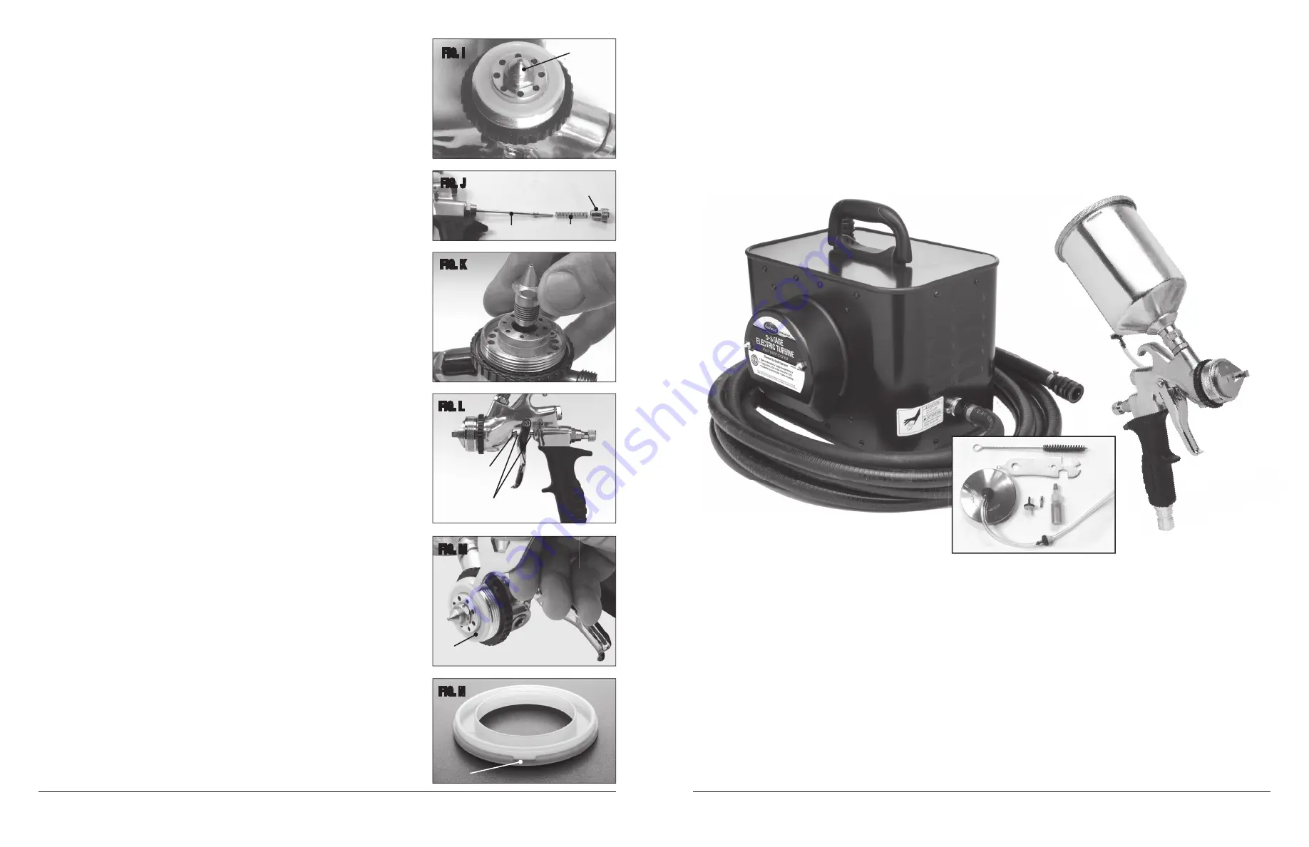
2. Remove the Air Cap
(Fig H)
and clean. Ensure that all the air holes in the air cap are clear.
3. Using a brush and solvent, remove any paint deposits on the outer surface of the Nozzle
(Fig I)
.
4. Unscrew and remove the Material Flow Adjusting Screw
(Fig J)
.
5. Remove the Needle spring
(Fig J)
.
6. Pull the trigger and then pull the needle
(Fig J)
out through the back of the spray gun.
7. Remove the Nozzle with the Wrench (Included)
(Fig K)
.
8. Clean both Nozzle and Needle assembly using appropriate solvent or water and a brush.
9. Make sure to lube (included) the Needle spring, the Air Valve Stem and the Gland Seal to
prevent the needle from sticking.
10. To adjust the Gland Nut
(Fig L)
, tighten until the needle sticks slightly when trigger is pulled,
then back off the nut about 1/8 turn. Do not over-tighten the gland nut or the needle will stick.
Do not under tighten or the Gland Seal will leak.
11. Check the Cup Top Gasket and replace if damaged. Always seat the cup top gasket fl at in the
cup groove. Failure to do this will allow the cup to drip and impair the spray pattern due to loss
of cup pressure.
ADVANCED DISASSEMBLY FOR REBUILD/REPAIR:
1. Follow steps above for partial cleaning.
2. To further disassemble the spray gun now that you have already removed the Air Cap Ring, Air
Cap, Fluid Nozzle and Needle assembly, locate the Air Cap Seal. To remove the Air Cap seal, lay
the Spray Gun on its side
(Fig M).
3. Locate the small groove on the Air Cap Seal
(Fig M)
. You can rotate the groove to a comfortable
position for removal. (3 o’clock or 9 o’clock).
4. Place the fl at tip of the wrench (included) in the Air Cap Seal groove. Push in and pry up until the
Air Cap Seal pops out
(Fig N)
. (Clean if necessary).
5. Remove the Air Distributor
(Fig O)
and clean if necessary.
6. Remove the Fan Adjustment Ring and Air Distributor Plate
(Fig P)
. The Air Distributor Plate is
attached to the Ring. These two pieces separate. Clean them both if necessary.
NOTE:
Make sure you reassemble the two pieces correctly or you will not have any fan
pattern adjustment.
7. Remove the Fan Adjustment Seal
(Fig Q)
. Clean if necessary.
FIG. I
INCLUDES
(1) HVLP Paint Gun with 0.8mm Needle/Nozzle set installed
(1) 24' x 3/4" Air Supply Hose
(1) Air Feed Tube w/Check Valve
(1) 1 Qt. Gravity Feed Paint Cup
(1) Wrench
(1) Air Feed Fitting
(1) 120 V/AC, 15 Amp, double insulated Turbine unit
(1) Cleaning Brush
(1) Replacement Check Valve
with 6', 14 Ga. power cord
(1) Paint Gun Lube
The
Eastwood 5-Stage Electric Turbine HVLP Paint System
is a powerful 5-Stage, fully self-contained, lightweight unit that provides clean, dry, warm air
to the HVLP type spray gun specifi cally designed to withstand the demands of the avid hobbyist and semi-professional. The true HVLP type gun design is fully
certifi ed and the unique annular fan control ring allows for precise adjustment and is fully certifi ed to use no more than 10 PSI.
SPECIFICATIONS
Paint Gun
• True HVLP with .8mm Needle/Nozzle set
• 1 Qt. Gravity Feed Paint Cup
• Operates on less than 10 PSI
Turbine Unit
• 120 Volt AC, 15 Amp power requirements
• 10 PSI output
• Gun Supply air dried and warmed to 20ºF above ambient intake air temperature
• 5-Stage Turbine
• Built-in air bleed system
• Gun Storage Receptacle
• 130 CFM output
FIG. J
FIG. K
FIG. L
FIG. M
FIG. N
Nozzle
Needle
Needle Spring
Fluid Control
Knob
Gland Nut
Lubricate
Air Cap
Seal
Groove


