background image

2


Eastwood Technical Assistance: 800.544.5118  >>  techelp@eastwood.com

To order parts and supplies: 800.345.1178  >>  eastwood.com 

7

READ INSTRUCTIONS! 

Thoroughly read and understand this instruction manual before using. Save manual for future reference.

SAFETY INFORMATION

ELECTRIC SHOCK HAZARD! 

•  Never operate or store unit in damp or wet conditions.
•  If an extension cord is required, a 25' cord is recommended not to exceed 50'. All extension cords must be 14 AWG or greater.
•  Always unplug Turbine Unit before refi lling gun cup, cleaning or servicing the Paint Gun’

HEALTH HAZARD! 

•  Avoid breathing vapors produced by Spray Gun. Always wear appropriate NIOSH approved breathing apparatus and use in a well 

ventilated area. 

•  Wear appropriate eye protection.
•  Wear solvent-resistant gloves.
•  This device emits high sound levels, the use of appropriate hearing protection is strongly recommended. Never operate the Turbine 

Unit without Paint Gun attached to hose.

FIRE AND EXPLOSION HAZARD! 

•  DO NOT allow fl ammable paint spray or vapors to enter the air intake of the Turbine Unit! Keep the Turbine Unit away from the painting 

area and in an elevated, secure position at all times.

•  Never use a coating or solvent with a fl ash point lower than 70°F (21°C). If unsure, refer to the MSDS for the particular products in question.
•  Do Not use near sparks, open fl ame or other potential ignition source.

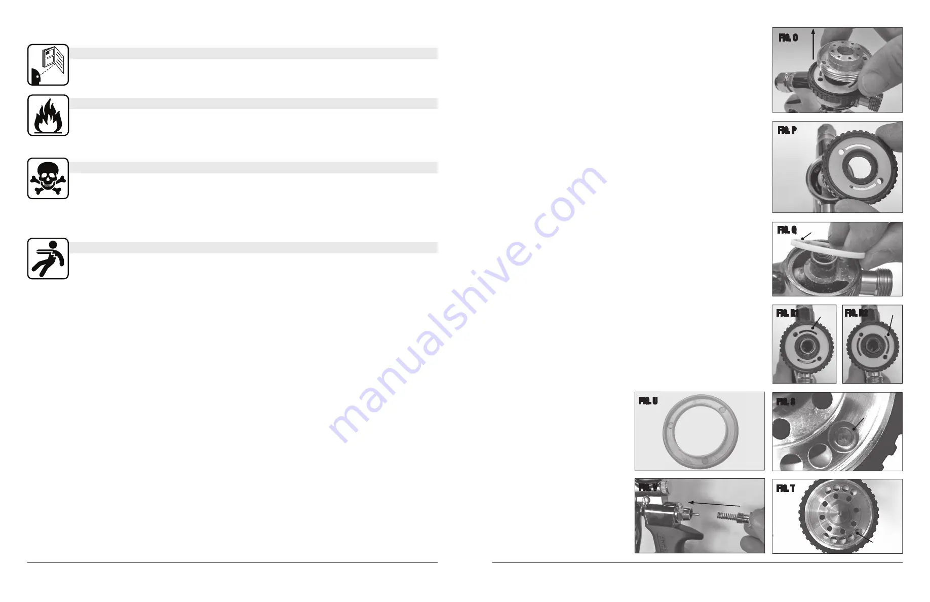
  REASSEMBLY FOR REBUILD/REPAIR


1.  Insert the Fan Adjustment Seal 

(Fig Q)

.


2.  Insert the Fan Adjustment Ring and Air Distributor Plate 

(Fig P)

NOTE:

 If you have


separated these two pieces it is critical that the white Air Distributor Plate is correctly 


re-inserted into the Fan Adjustment Ring. Note that the open slots on the Air Distributor


Plate must be visible through the holes of the Fan Adjustment Ring. Using the back end of 


the Needle assembly, move the Distributor Plate so that the round screw hole is at the 


5 o’clock position. DO NOT put the Distributor Plate and Fan Adjustment Ring together at  


this point. 


3.  Place the Air Distributor on top of the paired Fan Adjustment Ring and Air Distributor   


plate. Align the screw hole in the Air Distributor with the holes in the Fan Adjustment Ring 


and Air Distributor Plate 

(Figs R1 & R2)

.


4.  Place Air Cap Assembly over Stainless Steel Locating Pin 

(Figs S & T)

.


5.  Screw the Fluid Nozzle back onto the Spray Gun body, fi nger tight. Rotate the Fan 


Adjustment Ring to be sure it rotates freely and easily. Tighten the Nozzle slightly more 


with the wrench (included). Rotate Fan Adjustment Ring again. Do not over tighten the 


Fluid Nozzle as it will stop the Fan Adjustment Ring from rotating. If too tight, back off 


slightly. Be sure that the Fluid Nozzle is not too loose or leaking will occur.


6.  Insert the Air Cap Seal 

(Fig U)

. To insert, observe both sides of the seal. One side should 


have three small circles. This side goes toward the Spray Gun. Snap the Air Cap Seal onto  


the Air Distributor.


7.  Push the needle back into the spray gun. 


– Insert the Needle spring into the Material Adjustment Screw 

(Fig V)

.


– Install the Material Adjustment Screw with Needle Spring.


– Install air cap and air cap ring. Spray gun is now re-assembled and ready to use.

FIG. O

FIG. P

FIG. Q

FIG. R1

FIG. S

FIG. T

FIG. R2

FIG. U

FIG. V

Fan Adjustment Seal

Correct

Incorrect

Air Cap Seal

Stainless

Steel

Locating Pin

Counterbored 

Hole

Summary of Contents for 15334

Page 1: ... Paint Gun Handle into the Receptacle located on top of the Turbine Unit cabinet Fig Y Cover with a plastic trash bag and keep entire unit in a clean dry environment TROUBLESHOOTING Gun produces an uneven spray pattern or fan Paint or film buildup on Air Cap blocking air holes Unplug Turbine Unit and clean buildup from Air Cap Gun spits or sputters discharges large droplets Paint or film buildup o...

Page 2: ...t is critical that the white Air Distributor Plate is correctly re inserted into the Fan Adjustment Ring Note that the open slots on the Air Distributor Plate must be visible through the holes of the Fan Adjustment Ring Using the back end of the Needle assembly move the Distributor Plate so that the round screw hole is at the 5 o clock position DO NOT put the Distributor Plate and Fan Adjustment R...

Page 3: ...Ring Air Cap Fluid Nozzle and Needle assembly locate the Air Cap Seal To remove the Air Cap seal lay the Spray Gun on its side Fig M 3 Locate the small groove on the Air Cap Seal Fig M You can rotate the groove to a comfortable position for removal 3 o clock or 9 o clock 4 Place the flat tip of the wrench included in the Air Cap Seal groove Push in and pry up until the Air Cap Seal pops out Fig N ...

Page 4: ...ons and thoroughly mix the paint or coating material thinning or reducing may be necessary Follow coating manufacturer s instructions for thinning The use of a Paint Strainer when filling cup is strongly recommended to avoid possible Needle Nozzle blockage Fig F GUN SETTINGS Fan Pattern Orientation Make sure the Air Cap is properly oriented to produce a vertical fan spray pattern by viewing the HV...

Page 5: ...ons and thoroughly mix the paint or coating material thinning or reducing may be necessary Follow coating manufacturer s instructions for thinning The use of a Paint Strainer when filling cup is strongly recommended to avoid possible Needle Nozzle blockage Fig F GUN SETTINGS Fan Pattern Orientation Make sure the Air Cap is properly oriented to produce a vertical fan spray pattern by viewing the HV...

Page 6: ...Ring Air Cap Fluid Nozzle and Needle assembly locate the Air Cap Seal To remove the Air Cap seal lay the Spray Gun on its side Fig M 3 Locate the small groove on the Air Cap Seal Fig M You can rotate the groove to a comfortable position for removal 3 o clock or 9 o clock 4 Place the flat tip of the wrench included in the Air Cap Seal groove Push in and pry up until the Air Cap Seal pops out Fig N ...

Page 7: ...t is critical that the white Air Distributor Plate is correctly re inserted into the Fan Adjustment Ring Note that the open slots on the Air Distributor Plate must be visible through the holes of the Fan Adjustment Ring Using the back end of the Needle assembly move the Distributor Plate so that the round screw hole is at the 5 o clock position DO NOT put the Distributor Plate and Fan Adjustment R...

Page 8: ... Paint Gun Handle into the Receptacle located on top of the Turbine Unit cabinet Fig Y Cover with a plastic trash bag and keep entire unit in a clean dry environment TROUBLESHOOTING Gun produces an uneven spray pattern or fan Paint or film buildup on Air Cap blocking air holes Unplug Turbine Unit and clean buildup from Air Cap Gun spits or sputters discharges large droplets Paint or film buildup o...

Reviews: