background image

To order parts and supplies: 800.345.1178  >>  eastwood.com 

9

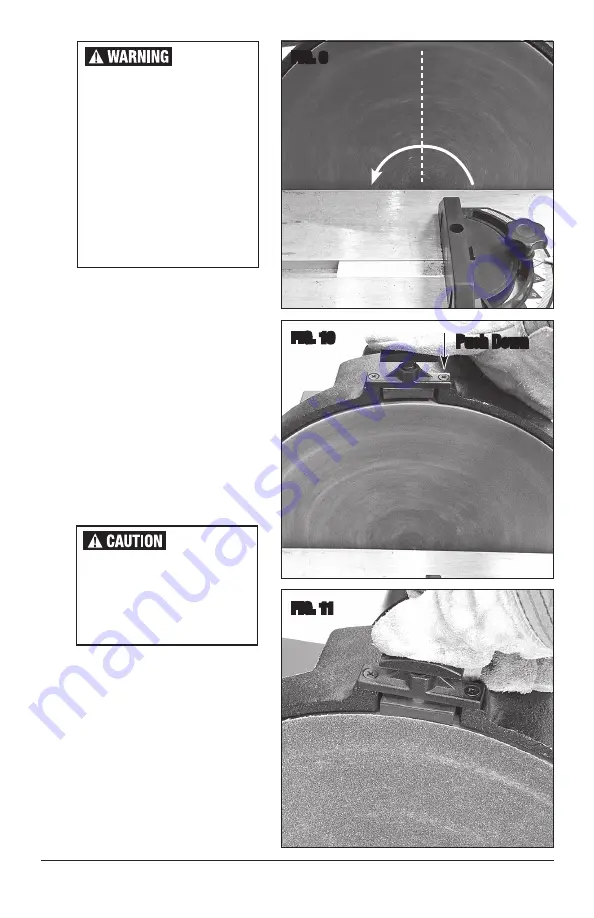
FIG. 9

FIG. 10

FIG. 11


Keep your body and any 
objects out of the path of the 
sparks which will be ejected 
at high velocity form the face 
of the Sander!

•  The Plunger Brake is intended to 

stop the rotating Disc immediately. 
To do so, push down firmly on the 
spring-loaded plunger to engage the 
Brake 

(FIGS 10 & 11)

.

•  Be sure the Yellow Safety Key is 

installed in the end of the Rocker 
Switch and move the Switch to the 
up “ON” position to run the Sander 
motor. Allow the Blade to reach full 
operating speed.

•  Slowly feed the material into the 

LEFT SIDE

 of the Disk letting the 

Sanding Disk do the sanding or 
grinding. DO NOT apply excessive 
force or serious personal injury, 
death and or serious damage to the 
Sander can occur.

WARNING!

Only Work  

From Left Side!

Push Down


The Disk rotates in a Counter-
Clockwise direction when 
viewed from the front.  
Always sand or grind using 
only the LEFT SIDE of the Disk 
(FIG 9). Working from the 
right side can cause objects 
to be suddenly and violently 
ejected outward causing 
severe personal injury and or 
property damage. 

Rotation

Summary of Contents for 21535

Page 1: ...12 DISC SANDER INSTRUCTIONS Part 21535...

Page 2: ...sc surface to allow quick Abrasive Disc changes TOOLS REQUIRED not included Phillips Screw Driver Straight Blade Screw Driver Square SPECIFICATIONS 120 VAC 8 Amp 1 2 HP motor Free Speed 1750 RPM 12 Sa...

Page 3: ...fers to your mains operated corded power tool or battery operated cordless power tool SAVE THESE INSTRUCTIONS 1 ELECTRICAL SAFETY a Power tool plugs must match the outlet Never modify the plug in any...

Page 4: ...es can reduce dust related hazards 3 POWER TOOL USE AND CARE a Do not force the power tool Use the correct power tool for your application The correct power tool will do the job better and safer at th...

Page 5: ...ly causing serious personal injury Always unplug the tool from the electrical supply before changing Sandpaper making adjustments to the tool or performing maintenance Sharp metal edges can cut Always...

Page 6: ...l handle back against spring pressure and use the 3mm Hex Key D to tighten FIG 1 INSTALL GUIDE PINS E TO SANDER HOUSING A Locate the Guide Pins E in the slots of the Platen Table Angle Brackets and th...

Page 7: ...bration levels while cutting If machine is to be operated on a bench it should be placed securely to prevent any chance of it working its way to the edge and falling Bolting in place or the use of C C...

Page 8: ...6 Always verify with a square for 90 or protractor for other angles FIG 7 Using the Miter Fence secure the workpiece and if desired adjust the angle of the sanding or grinding project FIG 8 Plug the...

Page 9: ...tch to the up ON position to run the Sander motor Allow the Blade to reach full operating speed Slowly feed the material into the LEFT SIDE of the Disk letting the Sanding Disk do the sanding or grind...

Page 10: ...securely around Sander Transport by using the built in carry handle at the top of the motor housing Store in a clean dry dampness free area preferably covered with plastic sheeting MAINTENANCE IMPORT...

Page 11: ...tension cord used Extension cords not recommended If necessary use only 16 Gauge or larger cord and limit length to 25 Sander Does Not Effectively Remove Material Abrasive Disk worn Check Abrasive Dis...

Page 12: ...e 240 Grit Copyright 2018 Easthill Group Inc 6 18 Instruction item 21535Q Rev 1 If you have any questions about the use of this product please contact The Eastwood Technical Assistance Service Departm...

Reviews: