6
Eastwood Technical Assistance: 800.343.9353 >> techelp@eastwood.com
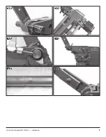
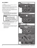
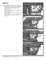
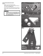
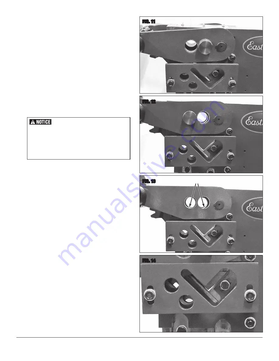
FIG. 11
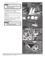
FIG. 12
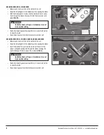
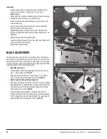
FIG. 13
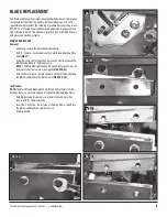
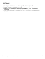
FIG. 14
ADJUSTMENTS
• Pivot Pin
The Eastwood Manual Ironworker design incorporates a moveable Pivot
Pin which modifies the cutting pivot point.
The factory installed position (rearward hole location) offers the greatest
leverage with the lowest Handle force required while causing greater lever
travel
(FIG 11)
. This is best when shearing thicker materials.
The alternate position (forward hole location) provides shorter lever travel
however it requires significantly greater lever force
(FIG 12)
. This may be
used on shearing lighter, thinner materials.
TO SWITCH PIVOT PIN POSITION:
- Remove Pivot Pin by griping the head firmly and rotating side to side
while pulling firmly. Carefully withdraw Pivot Pin and immediately
place it through the alternate pivot position
(FIG 12)
. Rotate Pivot
Pin side to side while pushing in.
• Right-Side, Round, Square and Angle Support Plate
The Right-Side Support Plate may be adjusted up or down to accommo-
date various sizes of material. To Do So:
- Loosen the 18mm Nuts
(FIG 14)
.
- Insert material to be sheared into the appropriate left side opening.
- Slide the Support Plate up or down as required to provide support
for the protruding material.
- Tighten the 18mm Nuts.
Do Not allow any components to move when
withdrawing Pivot Pin or Blade Drive Plate
misalignment can occur (Fig 13). Should this
occur, use of a screwdriver or magnet is advisable
to move the Blade Drive Plate back into alignment.
DO NOT use fingers!
Drive Plate
✓
✓


