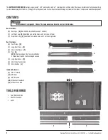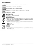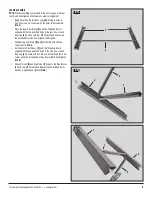
To order parts and supplies: 800.343.9353 >> eastwood.com
7
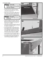
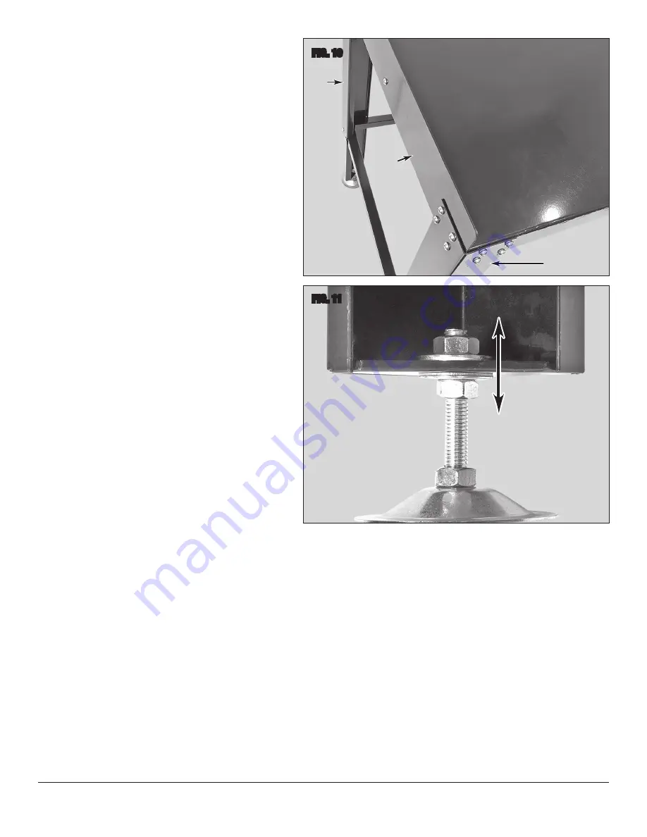
• With helper, carefully stand the Bench Assembly up on it’s
Feet then insert remaining eight M8 Socket Head Bolts through
the front both Front Legs
[B]
&
[C]
and Top
[G]
. Secure with
remaining eight M8 Self-Locking Nuts
(FIG 10)
.
• Check all components for squareness then final tighten all
hardware securely with the Included 5mm Hex Key
[L]
and
a 12mm wrench (not included).
LEVELING ADJUSTMENT
After placing the Bench in the chosen location, it may be necessary
to adjust the Feet to compensate for floor irregularities and achieve
levelness.
NOTE
: After leveling the Bench by adjusting Foot height, it is advis-
able to set the adjustment so that the front edge of the Top is 1/8” to
1/4” higher than the rear. This is so that loose objects will roll toward
the Fence and not off the front edge of the Top onto the floor.
• Using a 19mm wrench (not included) loosen the M12 Nuts
above the triangular Leg plates.
• Thread the M12 Nuts below the triangular Leg plates up or
down as required then retighten both Nuts with two 19mm
wrenches (not included)
(FIG 11)
.
MAINTENANCE
• Periodically clean Workbench of accumulated grease, fluids or
other debris.
• The Work Bench is finished in rugged powdercoating which
will provide many years of effort free beauty however it is
advisable to keep the finish clean and free from excessive dust
and dirt.
• Keep the Workbench in a clean and dry environment. Avoid
storing it in or exposing it to a damp or wet environment.
• Occasionally inspect all components for potential damage and
proper alignment. Check all hardware for tightness
• DO NOT use if damage is discovered.
FIG. 10
FIG. 11
✓
A
✓
✓
J
B
G
Thread UP to lower,
Down to raise
✓
✓


