background image

To order parts and supplies: 800.343.9353  >>  eastwood.com 

7

SET-UP

•  Note that The Eastwood 6” Buffer/ 

Polisher is supplied with a choice of  
2 handle mounting options:

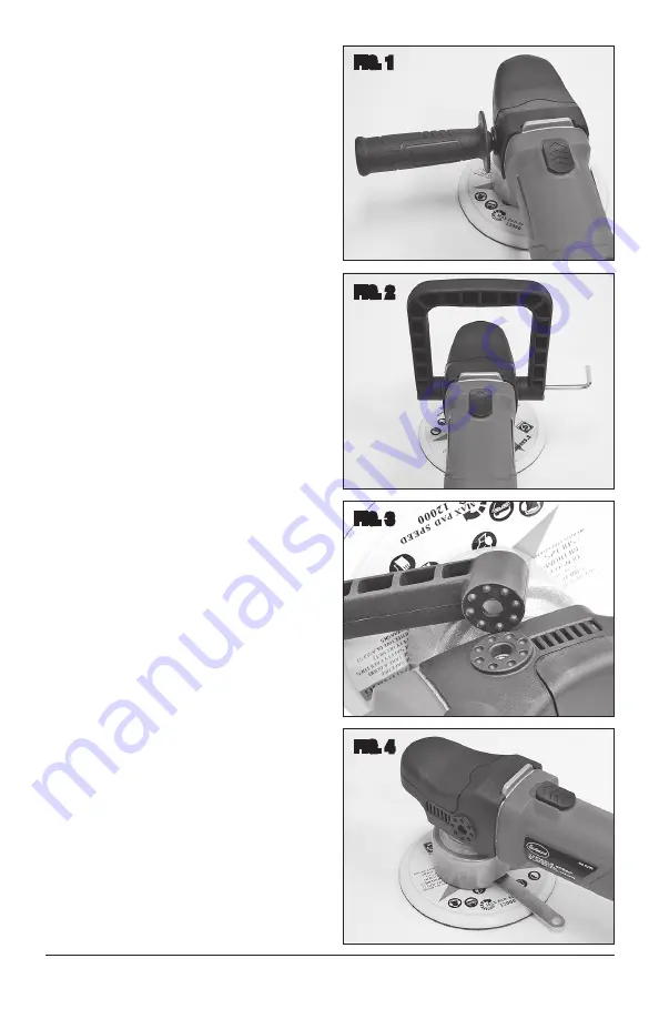
-  1st Option; Side Handle:

 Thread the 

Side Handle into one of the threaded 
holes at the side of the Buffer Head  

(FIG 1)

. Hand Tighten securely. 

NOTE:

 Attach to the left side for right-

handed users and to the right side for 
left-handed users .

-  2nd Option; “D” Handle:

 Place  

mounting holes over the threaded  
holes at the side of the Buffer Head 
and fasten with the supplied M8 Socket 
Head Cap Screws 

(FIG 2)

.  

NOTE:

 The Handle of the Buffer/Polisher 

has an array of round, raised features 
at the Mounting Flange area while the 
Buffer Head has an array of correspond-
ing depressions 

(FIG 3

). This allows for 

positive indexing of the Handle when the 
screws are tightened.

•  Slide the Spindle Flat Wrench over the Hex 

of the Spindle 

(FIG 4)

.

•  Thread the Backing Pad post into the Arbor 

and hold the Arbor Flat Wrench until it is 
securely tightened.

•  Withdraw the Arbor Flat Wrench.
•  Apply the appropriate work pad (Buffing 

Pad, Sanding Disc etc.) for the job.

•  Plug into a minimum 15-amp circuit.  

If using an extension cord, it must be  
AWG 14 or greater, no longer than 25’.

FIG. 1

FIG. 2

FIG. 3

FIG. 4

Summary of Contents for 32489

Page 1: ...VARIABLE SPEED 6 ORBITAL BUFFER POLISHER INSTRUCTIONS Part 32489 ...

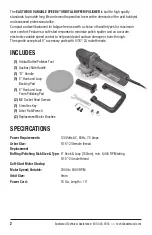
Page 2: ...e speed control to help avoid paint surface damage or burn through The spindle accepts all 6 accessory pads with 5 16 24 male threads INCLUDES 1 Orbital Buffer Polisher Tool 1 Auxiliary Side Handle 1 D Handle 1 6 Hook and Loop Backing Pad 1 6 Hook and Loop Foam Polishing Pad 2 M8 Socket Head Screws 1 5mm Hex Key 1 Arbor Flat Wrench 2 Replacement Motor Brushes SPECIFICATIONS Power Requirements 120 ...

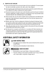
Page 3: ... all instructions Failure to follow all instructions listed below may result in electric shock fire and or serious injury The term power tool in all of the warnings listed below refers to your mains operated corded power tool or battery operated cordless power tool SAVE THESE INSTRUCTIONS 1 WORK AREA SAFETY a Keep work area clean and well lit Cluttered or dark areas invite accidents b Do not opera...

Page 4: ...r tool Do not use a power tool while you are tired or under the influence of drugs alcohol or medication A moment of inattention while operating power tools may result in serious personal injury b Use safety equipment Always wear eye protection Safety equipment such as dust mask non skid safety shoes hard hat or hearing protection used for appropriate conditions will reduce personal injuries c Avo...

Page 5: ...for misalignment or binding of moving parts breakage of parts and any other condition that may affect the power tools operation If damaged have the power tool repaired before use Many accidents are caused by poorly maintained power tools f Keep cutting tools sharp and clean Properly maintained cutting tools with sharp cutting edges are less likely to bind and are easier to control g Use the power ...

Page 6: ...cs Rotating Buffing Polishing discs can quickly abrade skin Keep hands and fingers away from rotating pad and always wear protective work gloves while sanding This Buffer Polisher can quickly and violently kick back or twist while oper ating causing severe hand and or wrist injury Do not apply excessive force tool while in use Use only on broad open spaces using care to avoid edges and corners If ...

Page 7: ... the supplied M8 Socket Head Cap Screws FIG 2 NOTE The Handle of the Buffer Polisher has an array of round raised features at the Mounting Flange area while the Buffer Head has an array of correspond ing depressions FIG 3 This allows for positive indexing of the Handle when the screws are tightened Slide the Spindle Flat Wrench over the Hex of the Spindle FIG 4 Thread the Backing Pad post into the...

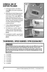
Page 8: ...nd it will spring back to the OFF Position The Switch has a Lock ON feature To engage move the Switch forward past the detent into the Locked ON position FIG 6 To release the Lock ON move the Switch back past the detent to the OFF position FIG 7 FIG 5 FIG 6 THUMBWHEEL SPEED NUMBER RPM EQUIVALENCY 1 2000 RPM 2 2700 RPM 3 3500 RPM 4 4800 RPM 5 5900 RPM 6 6400RPM The Thumbwheel Speed Control is infin...

Page 9: ...l conditions Individual requirements may vary Work Surface Abrasive Cleaning Disc Recommendations Machine Speed Removing moderate rust Removing old paint finish Rough shaping body filler P40 to P240 Grit 5000 to 6000 RPM 5 6 on Eastwood Buffer Dial Removing light surface rust Removing old paint finish Finish shaping body filler P320 to P600 Grit 4000 to 5000 RPM 4 5 on Eastwood Buffer Dial ...

Page 10: ...windows wheels and any black painted areas or plastic trim pieces using plastic sheeting and masking tape Note Flat or matte painted surfaces vinyl graphics and plastic trim can be white stained from the compound polish Carefully and fully read all labels of Compound and Polishes before beginning any work or ir reversible finish damage can result The use of Foam polishing pads is strongly recommen...

Page 11: ... Removing Wax Polish Application Mild Foam Finessing Pads and Abrasive free Wax or Polish 1400 to 1500 RPM 1 on Eastwood Buffer Dial Never push down on or apply pressure to the Buffer while running Let the spinning pad do the work Apply a several inch long bead of polishing compound to work surface or to face of pad NOTE Be sure to follow the buffing compound manufacturer s bottle instructions car...

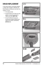
Page 12: ...ger is depressed the Motor Brushes are likely worn and need to be replaced To do so First unplug machine Remove the Motor Vent Panels one each side by removing the screws with a Phillips screwdriver FIGS 8 9 Remove the Motor End Housing by removing two additional Phillips screws adjacent to the Speed Control Wheel FIGS 10 11 FIG 8 FIG 9 FIG 10 FIG 11 ...

Page 13: ... keyed to the rectangular socket Release spring tension and carefully allow spring tab to exert pressure on the top of the brush Repeat above procedure for opposite brush Replace the Motor End Housing and the Motor Vent Panels and tighten screws The Brush Retaining Tab portion of the wound spring MUST be held in place while the Brush is removed DO NOT allow the spring to release If the Brush Retai...

Page 14: ...14 Eastwood Technical Assistance 800 343 9353 tech eastwood com NOTES ...

Page 15: ...to 25 Motor Brushes worn Replace Motor Brushes as described in this manual Excessive Noise and or Vibration Backing Disk loose on threaded Arbor Tighten Backing Disk onto Arbor Backing Disk cracked or damaged Replace Backing Disk as described in this manual Motor Overheats Excessive pressure being applied to Buffing Polishing Sanding Pad Allow Pad to cut by rotation alone Do Not Force Full face of...

Page 16: ...53 email tech eastwood com PDF version of this manual is available at eastwood com The Eastwood Company 263 Shoemaker Road Pottstown PA 19464 USA 800 343 9353 eastwood com ADDITIONAL ITEMS 16230 Chemical Guys Hex Logic Orange 6 5 Medium Heavy Cutting Pad 12019 Norton Liquid Ice Polishing Compound 16135 Griot s Complete Polish 32071 Chemical Guys Workhorse Towels 16143 True Power 8PC Microfiber Tow...

Reviews: