


4
Eastwood Technical Assistance: 800.544.5118 >> techelp@eastwood.com
To order parts and supplies: 800.345.1178 >> eastwood.com
13
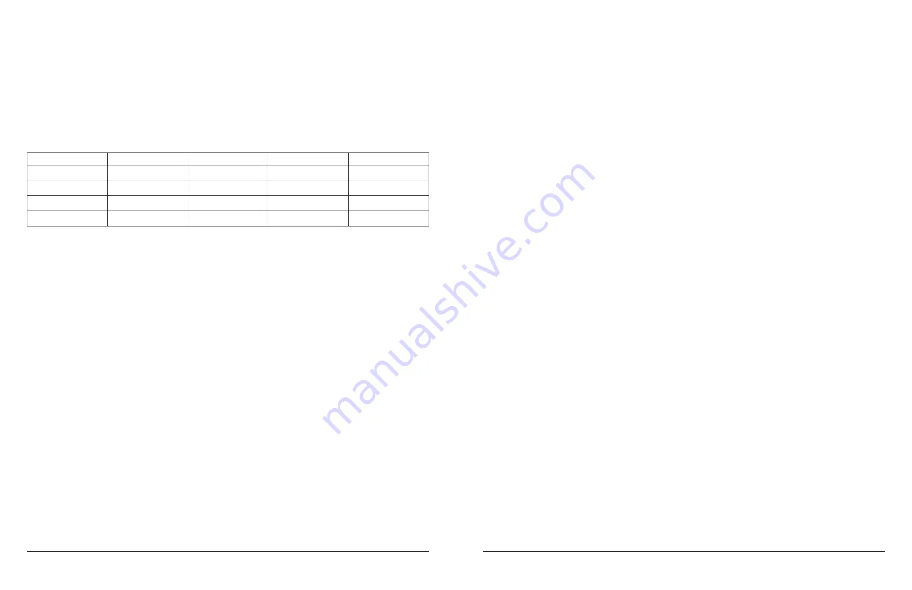
SPECIFICATIONS
TANK VOLUME
#51117
5 gallons/50-lbs. abrasive media
#51118
10 gallons/100-lbs. abrasive media
#51119
20 gallons/200-lbs. abrasive media
Hose Length (all)
8 ft. x 1/2" I.D.
Working Pressure (all)
60-125 psi
AIR & ABRASIVE MEDIA SUPPLY REQUIREMENTS
Hose I.D.
Hose Length
Nozzle I.D.
CFM @ 90 psi
Abrasive Use/Hr
3/8"
50 ft.
2mm
10
30-lbs.
3/8"
25 ft.
2.5mm
12
80-lbs.
1/2"
50 ft.
3mm
16
120-lbs.
3/4"
25 ft.
3.5mm
20
150-lbs.
2.
The second most common problem encountered with Abrasive Blasting is clumping and caking of media due to media
contamination due to moisture and/or large particle contamination.
This can occur in the Abrasive Flow Manifold located at the underside Tank outlet, in the Nozzle or in the Tank.
Remove source of moisture contamination.
Drain water trap frequently during use. Do not allow moisture to fill more than 1/2 the water trap bowl.
Do not leave water standing in water trap when done blasting.
Removal of moisture or particle contaminated media from the Tank may be necessary. To do so:
• Close the Abrasive Flow Valve.
• Release pressure on the Safety Trigger.
• Close the Throttling Valve and the Air Supply Valve.
• Disconnect air supply hose from abrasive blaster.
• Press the Safety Trigger until air stops flowing and Pressure Gauge reads “0".
• Open and remove Inlet Fill Cap.
• Invert blaster and shake out contaminated media.
• Refill Tank. The use of an Eastwood #22022 Blast Media Screen Sifter or a #50417 Abrasive Media Funnel Strainer is
highly recommended to help avoid possible media clogging.
To clear Nozzle:
• Close the Abrasive Flow Valve.
• Release pressure on the Safety Trigger.
• Close the Throttling Valve and the Air Supply Valve.
• Disconnect air supply hose from abrasive blaster.
• Press the Safety Trigger until air stops flowing and Pressure Gauge reads “0".
• Remove Nozzle and clear clog with a piece of wire or suitable object.
• Replace Nozzle and “retune” the blaster for optimal flow.
To clear Abrasive Flow Manifold at Tank Outlet:
• Close the Throttling Valve. This will divert full pressure to the Tank.
• Release pressure on the Safety Trigger. This will discharge a slow, soft stream of blast media.
• Reopen the Throttling Valve and “retune” the blaster for optimal flow.
To clear Abrasive Flow Manifold at Flow Port:
• Close the Abrasive Flow Valve. This will divert full pressure to the Flow Hose and Abrasive Hose.
• Release pressure on the Safety Trigger. This will discharge a rapid, thin stream of blast media.
• Reopen the Abrasive Flow Manifold and “retune” the blaster for optimal flow.
If the above steps fail to clear the clog:
• Close the Abrasive Flow Valve.
• Release pressure on the Safety Trigger.
• Close the Throttling Valve and the Air Supply Valve.
• Disconnect air supply hose from abrasive blaster.
• Press the Safety Trigger until air stops flowing and Pressure Gauge reads “0".
• Open and remove Inlet Fill Cap.
• Invert blaster and shake out contaminated media.
PARTS LIST
(1) Tank Assembly with pre-installed Outlet Manifold, Inlet Hose, Pressure Relief Valve and Fill Cap with Seal Ring
(1) Left and Right Handle Bars with Handgrips (Two Pieces in #’s 51117 & 51118, One Piece in #51119)
(1) Blast Hood
(1) Funnel
(1) Inlet Manifold and Moisture Separator Assembly
(1) Air Inlet Tube
(1) Pressure Gauge
(1) Air Inlet Valve
(1) Roll of Pipe Thread Tape
(1) 1/4" Female Quick Connect Fitting
(1) Blast Hose and Safety Valve/Nozzle Assembly (Inc. 2mm Nozzle)
(3) Additional Nozzles (2mm, 2.5mm & 5mm)
(4) 6mm x 1-3/8" (35mm) Long Screws
(4) 6mm Nuts
(4) 6mm Washers
(1) Front Support Leg
(1) Axle
(2) Wheels
(3) 1/2" x 1/4" Axle Washers
(3) 1-1/2" x 1/8" Cotter Pins
(1) Replacement 2-1/8" x 1-3/4" x 3/16" Fill Cap Seal Ring
(1) Replacement 11/16" x 3/8" Nozzle Seal Ring
(1) Instructions (#51116Q)


