background image

12


Eastwood Technical Assistance: 800.544.5118  >>  techelp@eastwood.com

To order parts and supplies: 800.345.1178  >>  eastwood.com 

5

MAINTENANCE

1. 

Drain water trap frequently during use. Do not allow moisture to fill more than 1/2 the water trap bowl. Do not leave water  

standing in water trap when done blasting.

2. 

Keep your Eastwood Abrasive Blaster clean, and protect it from damage.

3. 

Release pressure from the tank after each use.

4. 

When initially pressurizing, check for leaks at the tank top and at all hoses and fittings.

5. 

Leaking joints may be repaired by replacing worn or damaged parts and using Teflon tape at joints.

6. 

Check for worn abrasive hose and fittings. The Abrasive Control Valve, Abrasive Manifold, and all related parts after the abrasive 

flows from the tank are subject to rapid wear due to the flow of abrasive.

7. 

Watch especially for leaks, blistering, bulging or thinness of the hose. Replace any parts which appear worn.

TROUBLESHOOTING

1. 

The most frequent cause of poor Abrasive Blaster performance is improper set-up or “tuning” of the Abrasive Flow and  

Throttling Valves. 


The Abrasive Flow is a finely tuned combination of two adjustments (Throttling Valve and Abrasive Control Valve) which will vary 

widely with different media, air supply and atmospheric conditions.  


It is necessary to follow this “tuning” procedure at the beginning of every blasting job.  


NOTE:

 Operating the blaster with all valves wide open will result in decreased performance and effectiveness.  


Too much air flow/not enough media will result in a high velocity but ineffective stream. 


Too much media/not enough air flow will result in a soft, weak blast stream. 


To “tune” the flow:


a.

  Adjust air pressure with the Throttling Valve. The Throttling Valve controls the velocity of material flow.  


b.

  Adjust abrasive flow with Abrasive Control Valve. The Abrasive Control Valve controls the amount of abrasive introduced  


  into the stream. 


c.

  Increase Throttling Valve first in small increments followed by the Abrasive Control Valve second until an ideal smooth,  


  forceful flow is achieved. 


d.

  The above steps may need to be repeated in sequence until an ideal balance can be reached.

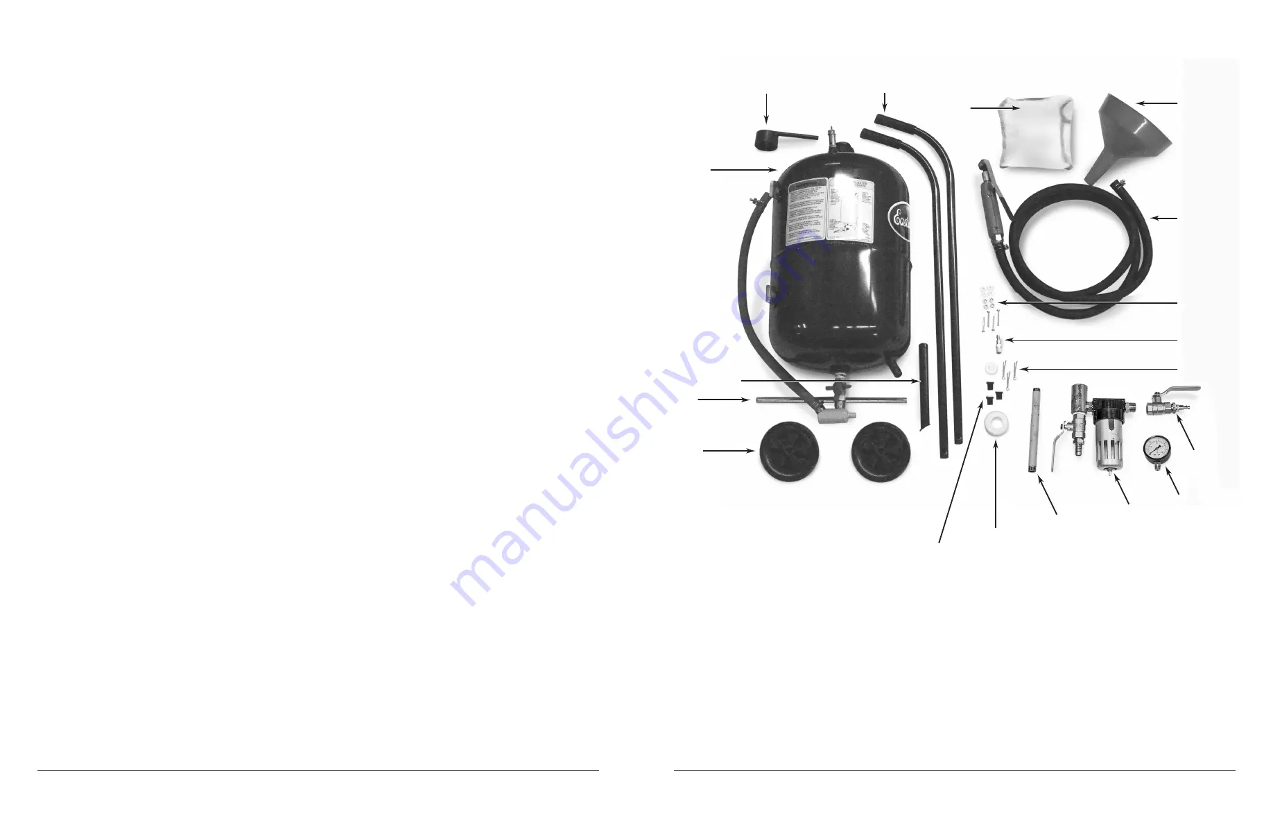
Fill Cap with Seal Ring

Tank 

Assembly

Funnel

Blast Hood

Blast Hose  

and Safety 

Valve/Nozzle 

Assembly

Hardware

1/4" NPT 

Quick Fitting
Cotter Pins

Air Inlet Valve

Wheels

Front  

Support Leg

Handle Bars

Nozzles

Pipe Thread Tape

Axle

Pressure

Gauge

Inlet Manifold/

Moisture 

Separator

Assembly

Air Inlet Tube

Summary of Contents for 51117

Page 1: ...PA 19464 USA US and Canada 800 345 1178 Outside US 610 718 8335 Fax 610 323 6268 eastwood com ACCESSORIES 22022 Abrasive Sifter Screen 11 50417 Abrasive Media Funnel Strainer 8 12123 Blast Nozzle Sealing Pads 3 Pack 51556 2mm Blast Nozzle 3 Pack 12111 2 5mm Blast Nozzle 3 Pack 12112 3mm Blast Nozzle 3 Pack 51557 3 5mm Blast Nozzle 3 Pack 11780 Replacement Safety Trigger Assembly Deadman Valve 1379...

Page 2: ... blast media par ticles have been known to cause cancer and other deadly diseases and must be avoided Always wear your blast hood NIOSH approved respiratory protection ANSI approved safety glasses and heavy duty canvas gloves when operating this equipment In addition levels of hazardous materials such as lead zinc chromate etc may be present in coatings being removed Additional protection may be r...

Page 3: ...90 psi DO NOT exceed 125 psi The safety valve is set to release at 125 psi If the safety valve releases stop all work immediately and release pressure from the tank see Releasing Pressure from the Tank section 3 The third most common cause of unsatisfactory Abrasive Blaster performance is insufficient CFM flow CFM Cubic Feet per Minute This is based on compressor output and is listed on all compre...

Page 4: ...nnect air supply hose from abrasive blaster Press the Safety Trigger until air stops flowing and Pressure Gauge reads 0 Remove Nozzle and clear clog with a piece of wire or suitable object Replace Nozzle and retune the blaster for optimal flow To clear Abrasive Flow Manifold at Tank Outlet Close the Throttling Valve This will divert full pressure to the Tank Release pressure on the Safety Trigger ...

Page 5: ...mbination of two adjustments Throttling Valve and Abrasive Control Valve which will vary widely with different media air supply and atmospheric conditions It is necessary to follow this tuning procedure at the beginning of every blasting job NOTE Operating the blaster with all valves wide open will result in decreased performance and effectiveness Too much air flow not enough media will result in ...

Page 6: ...e replaced immediately if its side walls develop leaks or show blisters in the surface Do not use if any of these problems are present NOZZLE REPLACEMENT 1 Disconnect air supply to Blaster 2 Release pressure in accordance to the Releasing Pressure from the Tank section above 3 While holding the Safety Trigger against spring pressure in the open position unthread the knurled Nozzle Retaining Collar...

Page 7: ...w this tuning procedure at the beginning of every blasting job NOTE Operating the blaster with all valves wide open will result in decreased performance and effectiveness Too much air flow not enough media will result in a high velocity but ineffective stream Too much media not enough air flow will result in a soft weak blast stream a Adjust air pressure with the Throttling Valve The Throttling Va...

Page 8: ...s not pressurized and the air gauge reads 0 To release the pressure from the Tank depress Nozzle Safety Trigger until air stops 2 Close the Air Supply Valve 3 Remove the Filler Cap 4 Using the included Funnel pour the selected abrasive media into the tank Eastwood 13792 Aluminum Oxide 90 Grit Abrasive Media is recommended for best performance CAUTION Do not fill the tank more than 3 4 full The use...

Page 9: ...s not pressurized and the air gauge reads 0 To release the pressure from the Tank depress Nozzle Safety Trigger until air stops 2 Close the Air Supply Valve 3 Remove the Filler Cap 4 Using the included Funnel pour the selected abrasive media into the tank Eastwood 13792 Aluminum Oxide 90 Grit Abrasive Media is recommended for best performance CAUTION Do not fill the tank more than 3 4 full The use...

Page 10: ...w this tuning procedure at the beginning of every blasting job NOTE Operating the blaster with all valves wide open will result in decreased performance and effectiveness Too much air flow not enough media will result in a high velocity but ineffective stream Too much media not enough air flow will result in a soft weak blast stream a Adjust air pressure with the Throttling Valve The Throttling Va...

Page 11: ...e replaced immediately if its side walls develop leaks or show blisters in the surface Do not use if any of these problems are present NOZZLE REPLACEMENT 1 Disconnect air supply to Blaster 2 Release pressure in accordance to the Releasing Pressure from the Tank section above 3 While holding the Safety Trigger against spring pressure in the open position unthread the knurled Nozzle Retaining Collar...

Page 12: ...mbination of two adjustments Throttling Valve and Abrasive Control Valve which will vary widely with different media air supply and atmospheric conditions It is necessary to follow this tuning procedure at the beginning of every blasting job NOTE Operating the blaster with all valves wide open will result in decreased performance and effectiveness Too much air flow not enough media will result in ...

Page 13: ...nnect air supply hose from abrasive blaster Press the Safety Trigger until air stops flowing and Pressure Gauge reads 0 Remove Nozzle and clear clog with a piece of wire or suitable object Replace Nozzle and retune the blaster for optimal flow To clear Abrasive Flow Manifold at Tank Outlet Close the Throttling Valve This will divert full pressure to the Tank Release pressure on the Safety Trigger ...

Page 14: ...90 psi DO NOT exceed 125 psi The safety valve is set to release at 125 psi If the safety valve releases stop all work immediately and release pressure from the tank see Releasing Pressure from the Tank section 3 The third most common cause of unsatisfactory Abrasive Blaster performance is insufficient CFM flow CFM Cubic Feet per Minute This is based on compressor output and is listed on all compre...

Page 15: ... blast media par ticles have been known to cause cancer and other deadly diseases and must be avoided Always wear your blast hood NIOSH approved respiratory protection ANSI approved safety glasses and heavy duty canvas gloves when operating this equipment In addition levels of hazardous materials such as lead zinc chromate etc may be present in coatings being removed Additional protection may be r...

Page 16: ...PA 19464 USA US and Canada 800 345 1178 Outside US 610 718 8335 Fax 610 323 6268 eastwood com ACCESSORIES 22022 Abrasive Sifter Screen 11 50417 Abrasive Media Funnel Strainer 8 12123 Blast Nozzle Sealing Pads 3 Pack 51556 2mm Blast Nozzle 3 Pack 12111 2 5mm Blast Nozzle 3 Pack 12112 3mm Blast Nozzle 3 Pack 51557 3 5mm Blast Nozzle 3 Pack 11780 Replacement Safety Trigger Assembly Deadman Valve 1379...

Reviews: