


6
Eastwood Technical Assistance: 800.544.5118 >> techelp@eastwood.com
To order parts and supplies: 800.345.1178 >> eastwood.com
11
TO STOP BLASTING
1.
While continuing to press and hold the Safety Trigger, turn the Abrasive Control Valve to the closed position (this is to prevent
any clogging.)
2.
When you notice only air (no abrasive) is coming out of the Safety Trigger Nozzle, you can stop the air flow by releasing the Trigger.
This ensures a clean and clog-free Abrasive Manifold, Hose, and Nozzle.
RELEASING PRESSURE FROM THE TANK
1.
When you are finished blasting, point the Safety Trigger Nozzle in a safe direction away from people, pets or anything around you
that may be harmed by direct or indirect high-pressure abrasive stream.
2.
Press and hold the Safety Trigger to expel any remaining abrasive material from the Abrasive Hose.
3.
Close the Abrasive Flow Valve.
4.
Release pressure on the Safety Trigger.
5.
Close the Throttling Valve and the Air Supply Valve.
6.
Disconnect air supply hose from abrasive blaster.
7.
Press the Safety Trigger until air stops flowing and Pressure Gauge reads “0".
CAUTION: Pay particular attention to the Abrasive Hose, the Abrasive Control Valve, and the Nozzles as they will wear out
much more quickly than the other pieces.
The Abrasive Hose needs to be replaced immediately if its side walls develop leaks or show blisters in the surface. Do not use
if any of these problems are present.
NOZZLE REPLACEMENT
1.
Disconnect air supply to Blaster.
2.
Release pressure in accordance to the “Releasing Pressure from the Tank” section above.
3.
While holding the Safety Trigger against spring pressure in the open position, unthread the knurled Nozzle Retaining Collar of the
Safety Trigger and remove the Retaining Collar, Nozzle and Rubber Seal
(Fig K)
.
NOTE:
Do Not lose the Rubber Seal that is placed
behind the ceramic base of the Nozzle.
4.
Insert replacement Nozzle into the Retaining Collar followed
by the Rubber Seal and again while holding the Safety Trigger
against spring pressure in the open position, thread the knurled
Nozzle Retaining Collar of the Safety Trigger onto the Safety
Trigger and tighten securely.
NOZZLE SEAL PAD REPLACEMENT
1.
Disconnect air supply to Blaster.
2.
Release pressure in accordance to the “Releasing Pressure
from the Tank” section above.
3.
Remove the Phillips head screw and nut then pull the Seal Pad
from the recess
(Fig K)
.
4.
Insert the replacement Seal Pad into the recess making sure the metal plate surface is parallel with the Nozzle outlet. Replace the
Phillips head screw and nut
(Fig K)
.
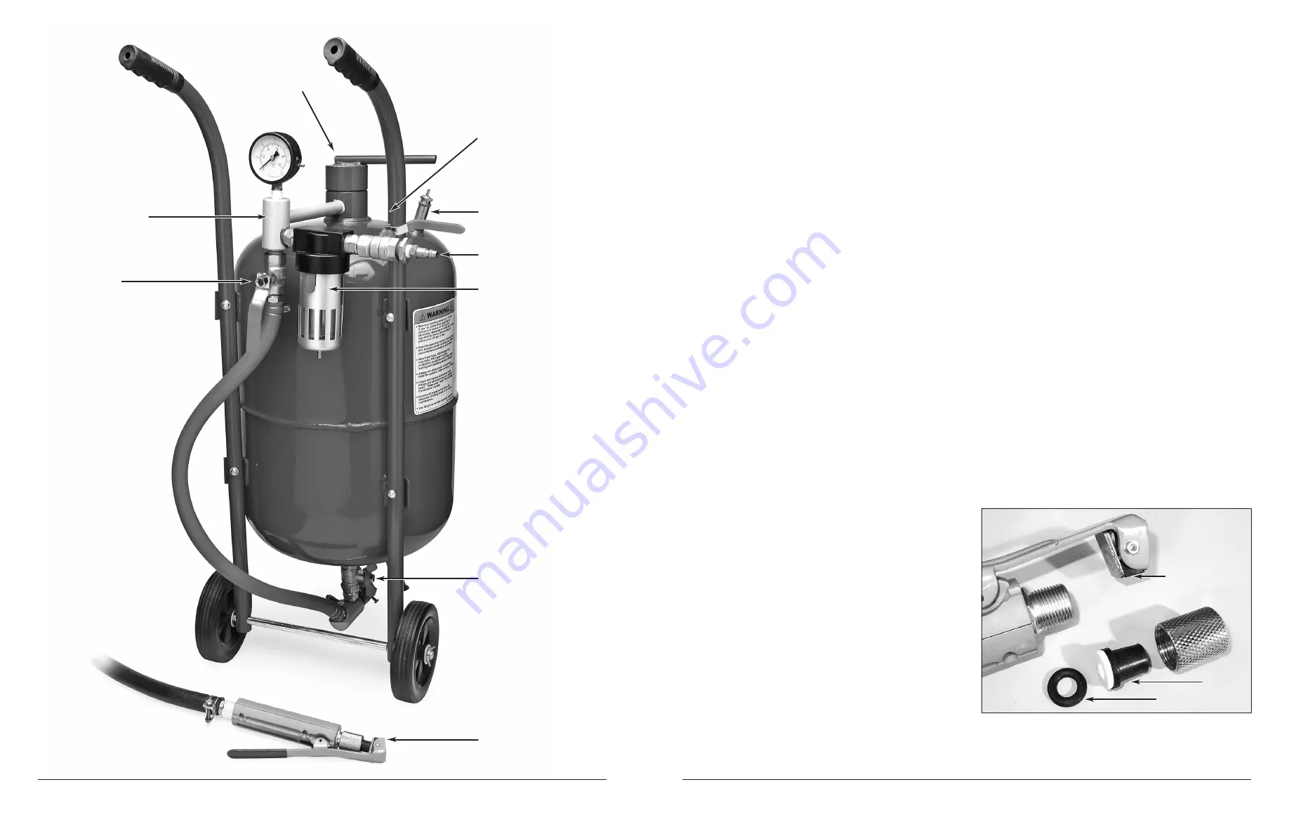
FIG. K
Nozzle Seal
✓
✓
✓
Nozzle
Seal Block
Filler Cap
✓
Inlet Manifold Assembly
Throttling Valve
Air Supply Valve
Pressure Relief Valve
Air Inlet
Moisture Trap
Abrasive Control Valve
Blast Hose and
Safety Valve Assembly
✓
✓
✓
✓
✓
✓
✓
✓


