background image

10


Eastwood Technical Assistance: 800.544.5118  >>  techelp@eastwood.com

To order parts and supplies: 800.345.1178  >>  eastwood.com 

7

TO BEGIN ABRASIVE BLASTING

IMPORTANT NOTES:

Start with all valves in the closed position. 
Following the instructions below will help prevent the 
formation of clogs in the Outlet Manifold, Abrasive Hose 
the Safety Trigger and Nozzle. 
Please note that as a result of many influencing variables 
such as the available compressed air supply CFM and 
pressure as well as the weight, density and grit size of the 
selected media combined with atmospheric pressure and 
humidity will all greatly affect the Blaster valve settings. 
The set-up process requires some repeated “trial and 
error” while following step 8 to achieve the best blaster 
performance.

1. 

Connect air compressor to the Inlet Connector.

2. 

Open Air Supply Valve fully.

3. 

Open Throttling Valve to approx. 1/2 way.

4. 

Check for leaks at the Filler Cap and along all hoses 

and fittings as the system pressurizes. If leaks are 

observed, release the pressure from the tank and 

repair immediately.

5. 

Point Safety Trigger Nozzle in a safe direction away 

from people, pets or anything around you that may 

be harmed by direct or indirect high-pressure  

abrasive stream.

6. 

Press and hold Safety Trigger until air is flowing 

through the Nozzle.

7. 

While holding the Safety Trigger open, slowly open the Abrasive Control Valve until abrasive material begins to flow out of the 

Safety Trigger Nozzle. Do not open Abrasive Control Valve any further at this point but follow procedure below.

8. 

Abrasive Flow Adjustment as follows: 

IMPORTANT NOTE:

 The Abrasive Flow is a finely tuned combination of two adjustments (Throttling Valve and Abrasive  

Control Valve) which will vary widely with different media, air supply and atmospheric conditions.  
It is necessary to follow this “tuning” procedure at the beginning of every blasting job.  

NOTE:

 Operating the blaster with all valves wide open will result in decreased performance and effectiveness.  

Too much air flow/not enough media will result in a high velocity but ineffective stream. 
Too much media/not enough air flow will result in a soft, weak blast stream. 

a.

  Adjust air pressure with the Throttling Valve. The Throttling Valve controls the velocity of material flow.  

b.

  Adjust abrasive flow with Abrasive Control Valve. The Abrasive Control Valve controls the amount of abrasive introduced  

  into the stream. 

c.

  Increase Throttling Valve first in small increments followed by the Abrasive Control Valve second until an ideal smooth,  

  forceful flow is achieved. 

d.

  The above steps may need to be repeated in sequence until an ideal balance can be reached.

9. 

Begin blasting.

10. 

Drain moisture trap frequently during use. Do not allow moisture to fill more than 1/2 the water trap bowl. Do not leave water 

standing in moisture trap when done blasting.
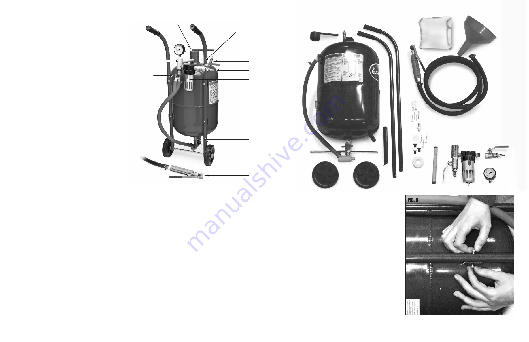
ASSEMBLY

1. 

Remove parts from container and verify that all components  

are present 

(Fig A)

.

2. 

Place Tank Assembly on a soft work surface for assembly with 

the welded-on Handle Bar mounting tabs facing upward 

(Fig B)

.

3. 

Place left and right tubular Handle Bars (

NOTE:

 2 pieces on  

Item #’s 51117 & 51118. One piece Handle on #51119) over  

the welded-on Handle Bar mounting tabs. The curved ends with 

rubber hand grips should point upward and be oriented toward 

the top of the Tank Assembly 

(Fig B)

.

4. 

Attach the left and right tubular Handle Bars to the 4 outward 

curved mounting tank mounting tabs with 4 supplied 1-3/8” long 

Phillips head screws and nuts. Note: Place screws through holes 

with nuts and washers facing forward to avoid possible future 

injury 

(Fig B)

.

5. 

Slide Axle through 2 holes in lower ends of tubular Handle Bars. 

FIG. A

FIG. B

Filler Cap

Inlet Manifold Assembly

Throttling Valve

Air Supply Valve

Pressure Relief Valve

Air Inlet

Moisture Trap

Abrasive Control Valve

Blast Hose and  

Safety Valve Assembly

Summary of Contents for 51117

Page 1: ...PA 19464 USA US and Canada 800 345 1178 Outside US 610 718 8335 Fax 610 323 6268 eastwood com ACCESSORIES 22022 Abrasive Sifter Screen 11 50417 Abrasive Media Funnel Strainer 8 12123 Blast Nozzle Sealing Pads 3 Pack 51556 2mm Blast Nozzle 3 Pack 12111 2 5mm Blast Nozzle 3 Pack 12112 3mm Blast Nozzle 3 Pack 51557 3 5mm Blast Nozzle 3 Pack 11780 Replacement Safety Trigger Assembly Deadman Valve 1379...

Page 2: ... blast media par ticles have been known to cause cancer and other deadly diseases and must be avoided Always wear your blast hood NIOSH approved respiratory protection ANSI approved safety glasses and heavy duty canvas gloves when operating this equipment In addition levels of hazardous materials such as lead zinc chromate etc may be present in coatings being removed Additional protection may be r...

Page 3: ...90 psi DO NOT exceed 125 psi The safety valve is set to release at 125 psi If the safety valve releases stop all work immediately and release pressure from the tank see Releasing Pressure from the Tank section 3 The third most common cause of unsatisfactory Abrasive Blaster performance is insufficient CFM flow CFM Cubic Feet per Minute This is based on compressor output and is listed on all compre...

Page 4: ...nnect air supply hose from abrasive blaster Press the Safety Trigger until air stops flowing and Pressure Gauge reads 0 Remove Nozzle and clear clog with a piece of wire or suitable object Replace Nozzle and retune the blaster for optimal flow To clear Abrasive Flow Manifold at Tank Outlet Close the Throttling Valve This will divert full pressure to the Tank Release pressure on the Safety Trigger ...

Page 5: ...mbination of two adjustments Throttling Valve and Abrasive Control Valve which will vary widely with different media air supply and atmospheric conditions It is necessary to follow this tuning procedure at the beginning of every blasting job NOTE Operating the blaster with all valves wide open will result in decreased performance and effectiveness Too much air flow not enough media will result in ...

Page 6: ...e replaced immediately if its side walls develop leaks or show blisters in the surface Do not use if any of these problems are present NOZZLE REPLACEMENT 1 Disconnect air supply to Blaster 2 Release pressure in accordance to the Releasing Pressure from the Tank section above 3 While holding the Safety Trigger against spring pressure in the open position unthread the knurled Nozzle Retaining Collar...

Page 7: ...w this tuning procedure at the beginning of every blasting job NOTE Operating the blaster with all valves wide open will result in decreased performance and effectiveness Too much air flow not enough media will result in a high velocity but ineffective stream Too much media not enough air flow will result in a soft weak blast stream a Adjust air pressure with the Throttling Valve The Throttling Va...

Page 8: ...s not pressurized and the air gauge reads 0 To release the pressure from the Tank depress Nozzle Safety Trigger until air stops 2 Close the Air Supply Valve 3 Remove the Filler Cap 4 Using the included Funnel pour the selected abrasive media into the tank Eastwood 13792 Aluminum Oxide 90 Grit Abrasive Media is recommended for best performance CAUTION Do not fill the tank more than 3 4 full The use...

Page 9: ...s not pressurized and the air gauge reads 0 To release the pressure from the Tank depress Nozzle Safety Trigger until air stops 2 Close the Air Supply Valve 3 Remove the Filler Cap 4 Using the included Funnel pour the selected abrasive media into the tank Eastwood 13792 Aluminum Oxide 90 Grit Abrasive Media is recommended for best performance CAUTION Do not fill the tank more than 3 4 full The use...

Page 10: ...w this tuning procedure at the beginning of every blasting job NOTE Operating the blaster with all valves wide open will result in decreased performance and effectiveness Too much air flow not enough media will result in a high velocity but ineffective stream Too much media not enough air flow will result in a soft weak blast stream a Adjust air pressure with the Throttling Valve The Throttling Va...

Page 11: ...e replaced immediately if its side walls develop leaks or show blisters in the surface Do not use if any of these problems are present NOZZLE REPLACEMENT 1 Disconnect air supply to Blaster 2 Release pressure in accordance to the Releasing Pressure from the Tank section above 3 While holding the Safety Trigger against spring pressure in the open position unthread the knurled Nozzle Retaining Collar...

Page 12: ...mbination of two adjustments Throttling Valve and Abrasive Control Valve which will vary widely with different media air supply and atmospheric conditions It is necessary to follow this tuning procedure at the beginning of every blasting job NOTE Operating the blaster with all valves wide open will result in decreased performance and effectiveness Too much air flow not enough media will result in ...

Page 13: ...nnect air supply hose from abrasive blaster Press the Safety Trigger until air stops flowing and Pressure Gauge reads 0 Remove Nozzle and clear clog with a piece of wire or suitable object Replace Nozzle and retune the blaster for optimal flow To clear Abrasive Flow Manifold at Tank Outlet Close the Throttling Valve This will divert full pressure to the Tank Release pressure on the Safety Trigger ...

Page 14: ...90 psi DO NOT exceed 125 psi The safety valve is set to release at 125 psi If the safety valve releases stop all work immediately and release pressure from the tank see Releasing Pressure from the Tank section 3 The third most common cause of unsatisfactory Abrasive Blaster performance is insufficient CFM flow CFM Cubic Feet per Minute This is based on compressor output and is listed on all compre...

Page 15: ... blast media par ticles have been known to cause cancer and other deadly diseases and must be avoided Always wear your blast hood NIOSH approved respiratory protection ANSI approved safety glasses and heavy duty canvas gloves when operating this equipment In addition levels of hazardous materials such as lead zinc chromate etc may be present in coatings being removed Additional protection may be r...

Page 16: ...PA 19464 USA US and Canada 800 345 1178 Outside US 610 718 8335 Fax 610 323 6268 eastwood com ACCESSORIES 22022 Abrasive Sifter Screen 11 50417 Abrasive Media Funnel Strainer 8 12123 Blast Nozzle Sealing Pads 3 Pack 51556 2mm Blast Nozzle 3 Pack 12111 2 5mm Blast Nozzle 3 Pack 12112 3mm Blast Nozzle 3 Pack 51557 3 5mm Blast Nozzle 3 Pack 11780 Replacement Safety Trigger Assembly Deadman Valve 1379...

Reviews: