8
Eastwood Technical Assistance: 800.544.5118 >> techelp@eastwood.com
To order parts and supplies: 800.345.1178 >> eastwood.com
9
OPERATION
WARNING:
Always wear your Blast Hood, NIOSH approved respiratory protection, ANSI-approved safety glasses, heavy duty canvas
gloves, long sleeves and long pants when operating the abrasive blaster.
WARNING:
Before operating your abrasive blaster, inspect each connection, double checking to make sure that all are tight and
properly sealed.
ABRASIVE SELECTION
The type of abrasive you choose will greatly influence the amount of time needed to clean a given surface area. Abrasive materials
include glass beads, aluminum oxide, and others.
NOTE:
Too large of a media particle size will clog the Nozzle outlet. To avoid potential
Nozzle clogging, use 60 grit abrasive or finer.
Never
exceed 60 grit media size. For best results, Eastwood recommends #13792,
Aluminum Oxide, 90 Grit as an excellent all purpose media.
• Make sure that the abrasive you use is thoroughly dry. Damp abrasive can cause clogging of your abrasive blaster.
• While you may reuse abrasive, remember that abrasive does wear out. After use, abrasive becomes smoother and rounder,
thus reducing abrasive effectiveness.
• Reusing abrasive may also cause clogging due to debris contained in the mixture from prior use. If you wish to re-use media,
it must be first sifted using an Eastwood #22022 Blast Media Screen Sifter.
WARNING: THIS BLASTER IS NOT INTENDED FOR USE WITH SILICA BASED ABRASIVES. SILICA BASED ABRASIVES HAVE
BEEN LINKED TO SEVERE RESPIRATORY DISEASE. ALWAYS USE SILICA SUBSTITUTES (SUCH AS EASTWOOD #22019 SILICON
CARBIDE, #13792 ALUMINUM OXIDE, OR #13780 GROUND GLASS) WHEN ABRASIVE BLASTING!
IMPORTANT NOTES
Check to make sure the abrasive is dry and clean so that it does not clog the unit. The use of an Eastwood #22022 Blast Media Screen
Sifter or a #50417 Abrasive Media Funnel Strainer is highly recommended to help avoid possible media clogging.
Never attempt to use blast media with a grit size greater than 60 or nozzle clogging will occur.
To avoid compressor pump damage, it is advisable to have your compressor located in another room away from the possibility of in
taking damaging dust and debris.
LOADING ABRASIVE
1. Before opening tank, be sure that it is not pressurized and the air gauge reads “0”.
To release the pressure from the Tank,
depress Nozzle Safety Trigger until air stops.
2.
Close the Air Supply Valve.
3.
Remove the Filler Cap.
4.
Using the included Funnel, pour the selected abrasive media into the tank. Eastwood #13792 Aluminum Oxide 90 Grit Abrasive
Media is recommended for best performance.
CAUTION:
Do not fill the tank more than 3/4 full.
The use of an Eastwood #22022 Blast Media Screen Sifter or a #50417 Abrasive Media Funnel Strainer is highly recommended
to help avoid possible media clogging.
If humidity in your region is 90% or more, only fill the tank half full and check the water trap more frequently.
5.
Thread on the Filler Cap, tightening it securely, assuring the Rubber Seal Ring is in place.
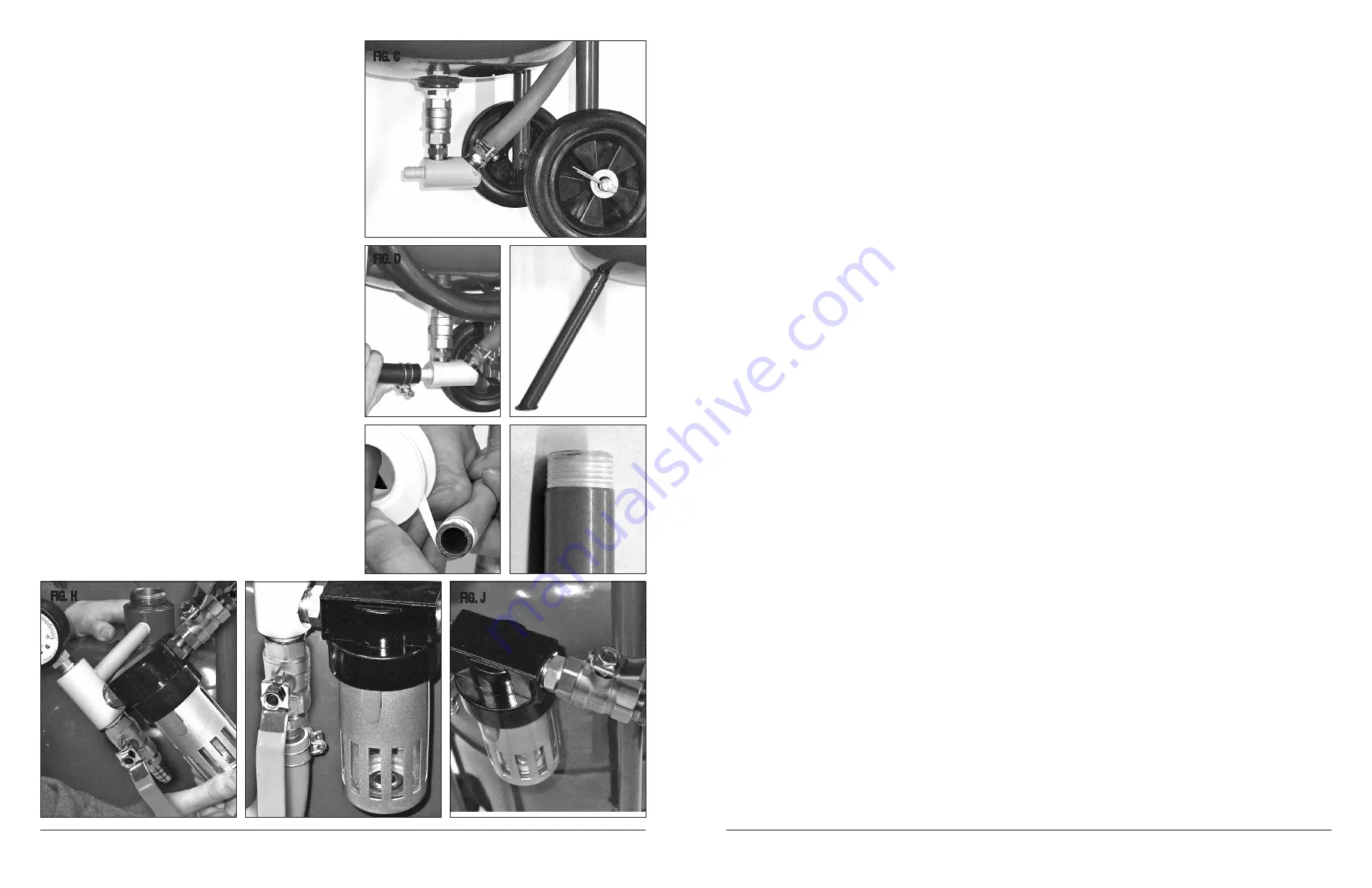
6.
Place 2 wheels with offset hubs inward onto axle ends with
washers on outboard ends. Push Cotter Pins through holes
in axle and bend split ends around axle
(Fig C)
.
7.
Slip the Hose Clamp over the Blast Hose (black), then slip
the open end of the hose over the hose barb on the Outlet
Manifold
(Fig D)
. Tighten Hose Clamp securely.
8.
Slide the Front Support Leg over the leg stub welded to the
front of the tank. Place a cotter pin through the holes and fold
split ends over
(Fig E)
.
9.
Apply Teflon Tape (included) to the Air Inlet Tube Threads by
wrapping it in clockwise direction as viewed from the open
end
(Figs F & G)
. Apply 4 to 5 layers of tape. Thread Air Inlet
Tube into the Air Inlet Manifold and the Moisture Seperator.
10.
Attach Inlet Manifold Assembly to the Tank Assembly by
threading the Air Inlet Tube into the threaded port in the side
of the Filler Cap base
(Fig H)
.
IMPORTANT NOTE:
Approx. 5 to 6 turns will be required
to fully tighten.
CAUTION:
Over tightening will cause permanent damage.
11.
Locate the Pressure Gauge and wrap the threads with Teflon
Tape. Insert the threaded end of the Pressure Gauge into the
Inlet Manifold and firmly tighten.
12.
Slip the Hose Clamp over the Flow Hose (red) then slip
the open end of the hose fully over the hose barb
(Fig I)
.
Tighten Hose Clamp securely.
13.
Apply Teflon Tape (included) to the 1/4" Female Quick
Connect fitting (included) by wrapping it in clockwise direc-
tion as viewed from the open end. Apply 4 to 5 layers of tape.
Thread it into the brass 1/2" x 3/8" NPT reducer (pre-installed
in the Inlet Manifold Assembly) and tighten securely
(Fig J)
.
FIG. C
FIG. D
FIG. F
FIG. G
FIG. H
FIG. I
FIG. J
FIG. E
NOTE:
Steps 9-10 are not necessary on the #51117, 50-lb. Blaster.


