12
Eastwood Technical Assistance: 800.343.9353 >> tech@eastwood.com
FIG. 21
FIG. 21
FIG. 22
FIG. 22
FIG. 23
FIG. 23
• Keep in mind that the metal forming is done by passing the metal over the anvil
while pulling it down and shaping it. The Wheel functions as a guide.
• It is normal to constantly adjust the anvil tension as you work. The goal is to have
it “not too tight yet not too loose.”
• Grasp the edges of the metal and continue to exert a gentle but firm downward
force while rolling it. With repeated rolling, a curvature will begin to appear in the
metal
(FIG 21)
.
• Track the wheel close between runs. The lines should fully overlap in the desired
forming area leaving no gaps
(FIG 22 LEFT SIDE)
. Too much space between runs
or too much pressure will result in a poorly formed panel
(FIG 22 RIGHT SIDE)
.
NOTE:
For illustrative purposes the patterns shown in
(FIG 22)
have been exag-
gerated. In practice they pattern should be much tighter to effectively form a
panel.
• Try not to repeatedly pass over the same point in the metal, which can work-
harden it, but keep it moving in a tightly spaced, sweeping “W” or “X” pattern
over the Anvil for best results. Note that the “W” pattern will produce a curve in
one direction only while the “X” will produce a compound curve or “bowl” effect.
• Practicing these techniques will have you well on the way to becoming an expert
English Wheeler! Continue practicing and you will be proud to have mastered a
nearly forgotten metalworking skill that few in the world possess!
LONG PANELS
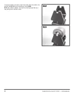
• When forming long panels, it may be optimal to change the direction you are
wheeling. This is simple with the Large Frame English Wheel as it is easily
indexed 90° so that the centerlines of the Wheel and Anvil are perpendicular to
the axis of the Frame
(FIG 23)
.
• Loosen the Anvil Tube set screws, Anvil Yoke set screws, and fully lower the
Jackscrew.
PINCH AND CRUSH HAZARD!
The Wheel weighs over 22 lbs. [10 kg]! Use extreme care when
handling. It is strongly recommended to have the help of an as-
sistant available while removing or installing the Wheel.
FIG. 24
FIG. 24
• Remove the Wheel from the Wheel Yoke by utilizing snap ring pliers to remove
one of the Wheel Axle snap rings
(FIG 24)
. Slide the Axle out while holding up the
wheel. The two spacers will also fall free as the Axle is removed. Set the Wheel,
Axle, snap ring, and spacers aside.


