8
Eastwood Technical Assistance: 800.343.9353 >> tech@eastwood.com
COMPRESSOR OPERATION
• Close the Water Drain Valve located at the underside of the Tank
(FIG 12)
.
• Move the Power Switch to the “ON” position
(FIG 1)
.
• Allow the Tank pressure to build to 145 PSI [10 bar] before each use. With the Air Compressor turned on, operation is automatic and under the control of
the internal Pressure Controller. It will turn off @ 145 PSI [10 bar] and automatically restart @ 115 PSI [7.9 bar].
The Eastwood Elite QST 30/60 Compressor is designed with a high efficiency, 1/2” Ball Valve at the air outlet with 1/2” FNPT
threads. It is strongly recommended to use 1/2” or larger air lines and fittings throughout your system. The use of 3/8” or smaller
lines is acceptable but will greatly hamper performance.
AIR LINE CONNECTION
It is strongly advisable to use a suitable high efficiency Air Regulator and Moisture/Oil Separator in a well-planned air-line layout after the Air Outlet Valve.
COMPRESSOR LOCATION
POSITIONING
• Locate all sides of the Compressor no less than 1 foot [0.3m] away
from any wall or closure.
• Maintain at least 2 feet [0.6m] of free space above the unit.
• Locate in a clean dry area away from other equipment which may
produce excessive heat or moisture.
• It is important to keep dust and debris from restricting air flow
through the compressor oil cooler. Do not operate compressor in a
small, enclosed area or under a cover.
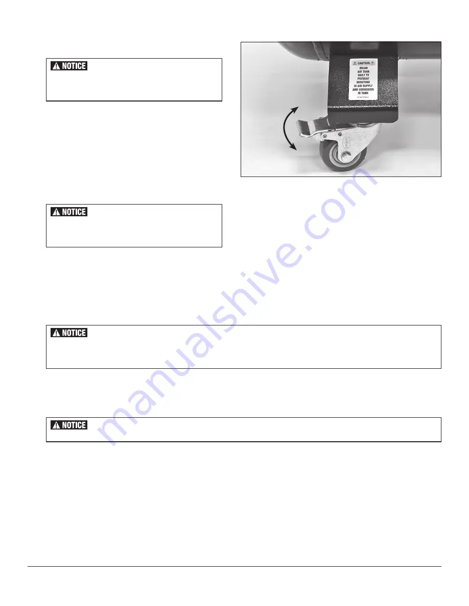
CASTER LOCKING
To Lock:
• Note that both of the Swivel Casters are equipped with brakes.
Push down on the Paddles to lock brakes
(FIG 13)
. Lift up on the
paddles to release brakes.
FIG. 13
FIG. 13
Lock
Unlock
The Eastwood Elite QST 30/60 Compressor is mounted
on Casters and can vibrate or move slightly during
operation. Always lock Casters before running.
The Eastwood Elite QST 30/60 Compressor gener-
ates heat during operation. Sufficient space must be
provided around the unit for cooling air circulation.
Unplug/disconnect from electrical power when not in use.


