6
cOMPONENTS AND cONTROLS
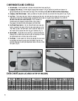
1. Power Switch
– The Power Switch is located at the left of the front panel (Fig A).
2. Amperage (Front Panel)
– Set the Output Amperage Knob marked “A” (Fig. A) located at right of the front panel to an
appropriate setting based on the thickness and type of the metal being welded.
(Refer to Data Chart for actual settings)
.
3. Amperage (Foot Pedal) Output
– Same operation as the panel control but is used while the foot pedal is in use (Fig B).
4. Gas Flow
– The included regulator limits the shielding gas flow from the bottle and also displays how much gas is left
in the bottle. The Gas Flow Indicator Gauge is located on the left side and is generally set between 12 to 20 SCFH.
(Refer to Data Chart for actual settings)
. This is explained in
further detail in the Preparing to Weld section of this manual.
The gauge on the right indicates the pressure left in the tank.
5. Foot Pedal/Panel Control
– The Foot Pedal/Panel Control selection
switch is located in the center of the front panel and when set in the
‘Foot Pedal’ position, the Foot Pedal control is activated. When set to
the ‘Panel Control’ position, the Torch Trigger is activated. (Fig. A)
6. Torch Switch
– The switch on the torch (Fig. C) controls starting and
stopping the arc. When using the torch switch the Amperage is set on
the adjustment knob on the front panel of the welder.
7. Foot Pedal
– The foot pedal is for starting and stopping the arc as well
as controlling the Amperage during the weld. When using the foot
pedal the Amperage is set by the adjustment knob on the side of the
foot pedal. (Fig. B)
DATA cHART
(ALSO LOcATED ON TOP OF wELDER)
Material
Material
Thickness
Polarity
Amperage
Tungsten Color
Tungsten
Diameter
Filler Metal
Filler Metal
Diameter
Torch Cup Size
Gas Flow
Rate (scfh)
Steel
1/16"
DC
45-80
Orange, Red, White
1/16"
ER70S-2
1/16"
1/4-3/8"
12
Steel
3/32"
DC
70-110
Orange, Red, White
1/16"
ER70S-2
1/16"
1/4-3/8"
12
Steel
1/8"
DC
75-125
Orange, Red, White
1/16"
ER70S-2
3/32"
1/4-3/8"
12
Steel
3/16"
DC
110-200
Orange, Red, White
3/32"
ER70S-2
1/8"
1/4-3/8"
14
Stainless Steel
1/16"
DC
50-90
Orange, Red, White
1/16"
ER308/308L
1/16"
1/4-3/8"
12
Stainless Steel
3/32"
DC
80-120
Orange, Red, White
1/16"
ER308/308L
1/16"
1/4-3/8"
12
Stainless Steel
1/8"
DC
85-140
Orange, Red, White
1/16"
ER308/308L
3/32"
1/4-3/8"
12
Stainless Steel
3/16"
DC
125-200
Orange, Red, White
3/32"
ER308/308L
1/8"
1/4-3/8"
14
FIG. A
FIG. B
FIG. C


