SETTINGS SELEcTION
With the materials selected of which you will be welding you can begin to set up the welder for the specific material.
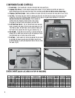
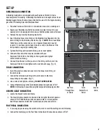
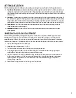
1. Foot Pedal / Panel Control –
Determine whether you will be using the switch on the torch or the foot pedal for arc
starting and stopping and put the selector switch in the appropriate position. Note that some connections changes
will be necessary also when switching the control type. These connection changes are covered in the Set-Up section
of this manual.
2. Amperage
– If welding using the switch on the torch to control the arc, Set the Output Amperage Knob marked “A”
(Fig. A) located at upper left of the top panel to an appropriate setting based on the thickness and type of the metal
being welded. (Refer to Data Chart for actual settings). If welding using the foot pedal to control the arc, it uses the
same operation as the panel control but is adjusted on the side of the foot pedal rather than the front panel. (Fig B).
3. Power Switch
– Once all of the settings have been selected and the torch assembled and ready to use, the
welder can be plugged in and turned on.
4. Shielding Gas Flow
– Set the Gas Flow Rate to the appropriate value with the Knob located at the left side
of the regulator.
SHIELDING GAS FLOw ADjuSTMENT
After connecting your Shielding Gas Regulator, the gas flow rate needs to be adjusted so that the proper amount of
Shielding Gas is flowing over your weld. If there is too little gas flow there will be porosity in your welds as well as
excessive spatter, if there is too much gas flow you will be wasting gas and may affect the weld quality. The included
regulator has 2 gauges on it; the gauge on the left is your flow rate while the gauge on your right is your tank pressure.
1. Open your Shielding Gas tank valve all the way.
2. Adjust the knob on the regulator to ~20 CFH.
3. Turn on the welder and trigger the torch switch which will start the gas flow.
4. As you trigger the torch switch you will notice that as the gas flow starts the needle on the gauge drops to a
steady reading. The reading while flowing is the value you want to read.
5. The gas flow should be set to 12-20 CFH while flowing. The CFH (Cubic Feet per Hour) scale is the inside scale
in red on your flow gauge. 20 CFH is the most typical flow rate but it may need to be adjusted in some cases
depending if there is a slight breeze or some other instance where additional shielding gas is required to
prevent porosity in the weld.
6. When finished welding remember to close the gas valve on the bottle.
9


