FREEPHONE 0800 394 222
sales@easyaccess.co.nz www.easyaccess.co.nz
Check each bolt end to ensure there are no more than two turns of thread showing past the nyloc
nut.
note: the support surface that is used to ‘set’ the platform must be exactly level to ensure the platform
doesn’t ‘rock’ when in use. if the platform does ‘rock’ a little, loosen the bolts attaching the platform/ladder frame
to the back leg frame; ‘settle’ the platform and re-tighten.
SteP 9: Planbrace
WHdp07-11: these models have a 40 x 15mm extrusion planbrace which attaches to the underside of the
bottom side braces, on each side across the plan of the ladder. nuts are preset into the base of the bottom side
braces which the m8 x 40 button head bolts are inserted into. tighten the bolts firmly into the nutserts.
SteP 10: Corner Braces
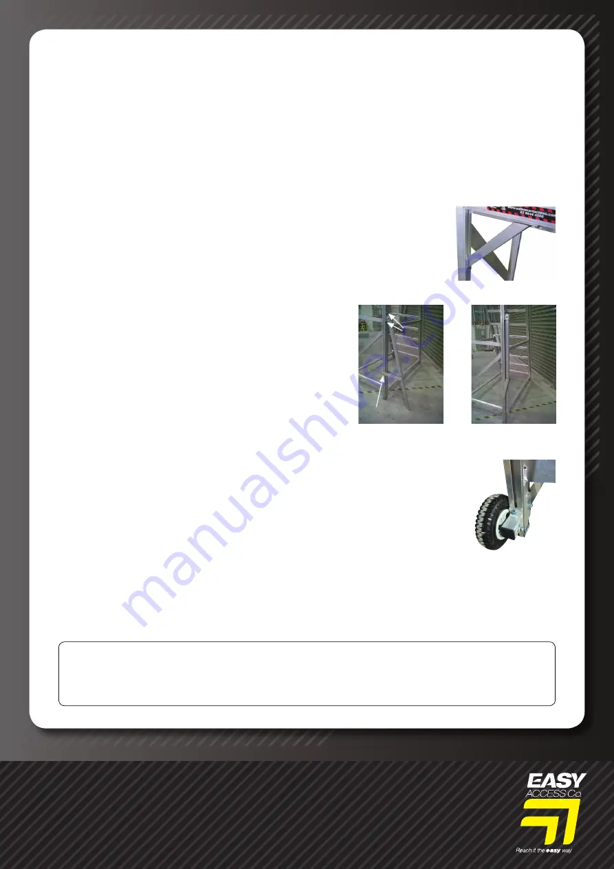
WHdp04 - 11 models have a corner brace each side that attach to the base of the
platform side extrusion and the back slot on each back frame stile. position them at
an equal 45º angle, attach with t-bolts and tighten 10mm nyloc nuts firmly.
SteP 11: Stabilizer arms
WHdp09 - 11 may have stabilizer arms fitted.
these are to be used at all times unless the platform is closely
adjacent to a fixed structure. the various components attach
to the back frame using using m10 x 20 bolts, (sliding plates),
t-bolts, (side arms) and nyloc nuts. if the m10 x 20 bolts have
not been inserted into the slots in the sides of the back leg
frame prior to assembly they may be inserted now by removing
the foot cap..
Note: the stabilizer arms must be resting firmly on the
support surface and the nyloc nuts holding the slide
plates firmly tightened before use. The pictures show
an arm engaged (14) and closed (15).
SteP 12: Wheels
the platform has two wheels to enable it to be relocated easily. these are attached
to the front of the back leg frame using t-bolts and nyloc nuts
(16)
. the wheel
should rest lightly on the support surface before the nyloc nuts are tightened.
Note: ensure the back leg frame base is still firmly resting on the support
surface after the wheels have been attached.
the manufacturers or supplier will not accept liability for injury or damage resulting from product failure
due to misuses, abuse, faulty installation and alteration, lack of reasonable care, lack of adequate training,
use not listed under these Operational Safety instructions or any other failure not related to defects in
materials or manufacture.
aSSemBly InStruCtIonS
YOUR WORK PLATFORM IS NOW FULLY ASSEMBLED. PLEASE ENSURE THAT ALL USERS
HAVE READ THE OPERATIONAL AND SAFETY INSTRUCTIONS LABEL ON THE PLATFORM PRIOR
TO USING IT.
tHank yOu fOr takinG tHe time tO read tHeSe inStructiOnS, and fOr purcHaSinG tHe eaSy
acceSS WHdp Heavy duty WOrk platfOrm.
16.
15.
14.
T-Bolt
M10 x 20
Bolts
Stabilizer arm in use
Stabilizer arm stowed


