background image

 11

Display unit

Measurement 

file handling

Save file

1. Select 

 and 

 to save your measurement. 

2. 

Enter a file name. The date and time will automatically be added to the file name. 

The measurements that you save will be available to other users as well. 

3. Press 

 to save the file.

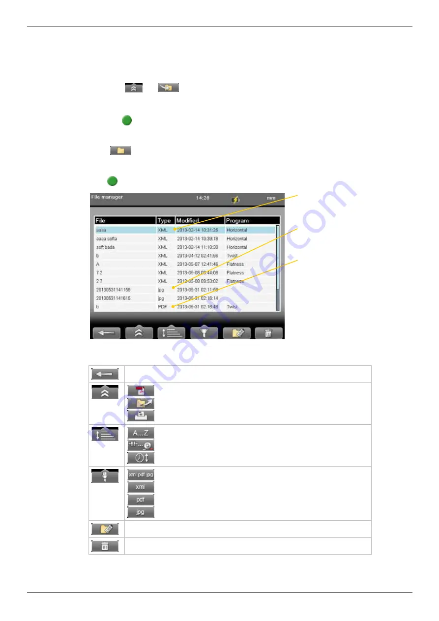
File manager

Select 

 (found on the start view and Control panel) to open saved measurements. 

The File manager is displayed. Here you can easily when and from which program the 

file was saved. 

Press 

 to open a measurement file.

Function buttons

Back

 to previous view. 


“Report” on page 

13.  


“Open file as template” on page 12

.


“Print file (Optional)” on page 13

.

 Sort files alphabetically.


 Sort files by measurement program.


 Sort by time.

 Show all files.


 Show only xml files. 


 Show only pdf files.


 Show only jpg files.

“Copy file to USB memory” on page 12

Delete files. Delete all 

displayed

 files or only selected file. 

xml


A measurement file. 

jpg


“Screen dump” on page 8

PDF


A report. The PDF report can not be 

opened in the Display unit. 

PDF is not available for E420.

Summary of Contents for E530

Page 1: ...MANUAL English 05 0560 Revision 5 0 System version 6 0 E530 ...

Page 2: ......

Page 3: ...ble 9 Charge the Detectors 9 Calculator 10 Measurement file handling 11 Save file 11 File manager 11 Open file as template 12 Copy file to USB memory 12 Barcode 12 Print file Optional 13 Report 13 Download file to PC 13 Control panel 14 Filter 14 Unit and resolution 15 Detector rotation 15 Date and time 15 Language 16 User 16 Backlight 16 Automatic power off 17 VGA 17 System update 18 License 19 B...

Page 4: ... Measure using EasyTurn 47 Measure using 9 12 3 48 Result 49 Result Machine view 49 Result Table view 50 Result Graph view 51 Lock feet pair 52 Best fit and Manual fit 52 Uncertain coupling 52 Adjust 53 Tolerance 55 Thermal compensation 56 SOFTFOOT 57 VERTICAL 59 Preparations 59 Measure 60 Result 61 Adjust machine 62 BTA 63 Preparations 64 Mount the units 64 Enter distances 65 Measure 66 VIBROMETE...

Page 5: ...peration is subject to the following two conditions 1 this device may not cause harmful interference 2 this device must accept any interference received including interference that may cause undesired operation Disposal of old electrical and electronic equipment Applicable through out the European Union and other European countries with separate col lection programs This symbol found on product or...

Page 6: ...o Damalini is not included in the warranty Note Before delivery of the product for warranty repair it is the responsibility of the buyer to backup all data Data recovery is not included in the warranty service and Dama lini is not responsible for data that may be lost or damaged during transit or repair Lithium Ion battery limited warranty Lithium ion batteries inevitably lose power during their l...

Page 7: ...vice and calibration Our Service centres will quickly assist you if your measurement system need to be repaired or when it is time for calibration Our main Service centre is located in Sweden There are several local Service centres that are certified to carry out limited service and repair Contact your local Service centre first before sending your equipment for service or repair All Service centr...

Page 8: ...D75 Compatibility The E series is not compatible with previous analogue units from the D series You can however continue to use previous brackets Disclaimer Damalini AB and our authorized dealers will take no responsibility for damage to machines and plant as a result of the use of Easy Laser measurement and alignment systems Copyright Damalini 2013 We might change and correct the manual in later ...

Page 9: ... reset the Display unit D A B C Navigation buttons Function buttons Numeric buttons LED signals OK buttons A Connection for external power B USB A master Use for USB memory C USB B slave Use for connecting to a PC D Connection for Easy Laser equipment ...

Page 10: ...way Press to select the currently selected icon for example Function buttons The icons above the function buttons change depending on which view is currently displayed on screen Below is a list of the most common icons Back to previous view Press and hold to leave current program Back There is no previous view Leave the current program More Contains a submenu with general functions such as Control...

Page 11: ...ng Displayed when the coordinates has been rotated in the detector Go to Control panel to rotate coordinates Display unit charging Indicating that a power adaptor is plugged in Hourglass The Display unit is in the middle of a task Measurement progress Time is depending on which filter you have selected Selected filter Peripheral Indicates that a peripheral device is plugged in such as a projector ...

Page 12: ...ile handling on page 11 LED lights Right indicator Yellow Flashing The internal battery in the Display unit is charging Left indicator Left indicator has several functions and colours Red Blue Quick flashing Reprogramming the system Red Flashing Warning for example low battery Blue Flashing Searching for detectors equipped with Bluetooth Fixed light Connected to detectors equipped with Bluetooth G...

Page 13: ...nnect the measuring units by using cable Charge the Display unit The Display unit can be used from 10ºC to 50ºC Charge the Display unit within the temperature range of 0ºC to 40ºC Note If you shut the Display unit off while charging it will charge faster Power adaptor With the power adaptor plugged in you can keep on working A PC via USB cable While you have this connection you can open the files ...

Page 14: ...menu Use OK button as equal sign Unit converter The unit converter is found on the Start view and Control panel 1 Select and to open Unit converter 2 Select a category Move using the navigation buttons up and down 3 Press navigation button right The result column is activated 4 Select a unit to convert from 5 Enter an amount The other units are recalculated In the example below one inch is selecte...

Page 15: ...an easily when and from which program the file was saved Press to open a measurement file Function buttons Back to previous view Report on page 13 Open file as template on page 12 Print file Optional on page 13 Sort files alphabetically Sort files by measurement program Sort by time Show all files Show only xml files Show only pdf files Show only jpg files Copy file to USB memory on page 12 Delete...

Page 16: ... created on the USB memory The file is saved in the folder Damalini archive Barcode Save file with barcode The barcode scanner is not included in all systems The first time you measure a machine you stick a barcode on the machine and save the measurement together with the scanned barcode Next time you align the same machine all you need to do is scan the barcode and all machine data is read 1 Scan...

Page 17: ... your logo logo jpg The default logo has the proportions of 230x51 pixels 2 Connect the Display unit to your PC using the USB cable 3 Place your image in the Display unit s folder Damalini custom reports logo File extensions for example jpg are often hidden in the Explorer window To dis play file extensions do the following Open an Explorer window and press Alt to show menu Select Tools Folder opt...

Page 18: ...lected filter Measurement progress Time is depending on which filter you have selected Select filter Use as short a time as possible that still produces acceptable stability during the measurement Default is set to 1 Normally you will use a filter value of 1 3 If you set the filter type to 0 no filter will be used Use the numerical buttons 3 6 and 9 to set the filter In the Filter view but also wh...

Page 19: ...0 only 0 01mm is possible Detector rotation Personal setting The coordinate system can be rotated 90º Select to open the Detector rotation view When you have rotated the coordinates a warning is displayed on the Status bar Detector rotation will only affect detectors with two axis Detector rotation view Date and time Select to open the Date and Time view Set the date and time Default is set to Cen...

Page 20: ...ght Personal setting Select to open the Backlight view Use the navigation buttons to move between the fields Press to save changes When backlight is off the left LED signal will flash to indicate that the Display unit is still on Backlight level Adjust the backlight to make it easier to read in bright sunlight Remember however that a high contrast consume more battery power Default is set to 50 Re...

Page 21: ...er off view Note Measurements in progress will not be saved in the event of an Automatic power off Information Select to display the information regarding serial number and version of the equipment Information view VGA Not available on all systems Makes it possible to show display unit screen image with a projector for example in a training context Must be factory installed on order Select to open...

Page 22: ... menu is displayed Note During restart the screen turns black for up to one minute When the main menu is displayed it can freeze no response when you press buttons If this happens press the On Off button for at least 15 seconds to restart the Display unit Font package Some of the early E series systems was not installed with Unicode fonts To install the latest system updates you need to install th...

Page 23: ... USB 1 Save the downloaded license file to a USB memory stick 2 Insert the USB memory stick in the Display unit 3 Select and to display the License view 4 Select to search for licenses 5 Press to import license Save file to Display unit 1 Connect the Display unit to a PC 2 Save the license file to the root of the Display unit s storage 3 Select and to display the License view 4 Select to search fo...

Page 24: ...d select The unit will automati cally be connected when you start a measurement program 5 Press to save changes and to leave the Bluetooth view 6 Enter a measurement program The Display unit will connect to the selected units While connecting the left LED indicator is flashing with a blue light which will turn to a fixed blue light once connected 7 An icon on the status bar will indicate how many ...

Page 25: ... to use to 4 Make sure that the other units are set to 5 Enter a measuring program The Display unit will connect to the selected unit This may take a couple of minutes Note Remove Bluetooth unit from the Measuring unit before putting the equipment in the carrying case If attached it will discharge the Measuring unit Bluetooth information This device contains FCC ID PVH0925 IC 5325A 0925 This devic...

Page 26: ...22 ...

Page 27: ...r play and clearance in the bearing Vertical For alignment of vertically mounted machines 9 12 3 Measuring positions are registered at positions 9 12 3 o clock EasyTurn Measuring positions are registered within 40º Horizontal For alignment of horizontal machines Values Shows live readings from S and M units BTA For alignment of belt and chain drives VIbrometer Shows the vibration level in mm s and...

Page 28: ...24 ...

Page 29: ...lete registered values Print report on thermal printer optional equipment See Streaming values on page 29 Set current value to zero Half displayed value Return to absolute value Only available after zeroing or halving Choose how to display values Use left and right navigation button to switch between two or more detectors when only one target is displayed Live vertical values Serial number Toleran...

Page 30: ...ttons to move between the fields and to change the tolerance 3 Press OK Live values and marking displayed in green when within tolerance Live values displayed in red when outside tolerance Zoom 1 Select and to zoom 2 Select a zoom factor between 1 5 Use navi gation buttons to increase or decrease zoom factor 3 Press OK Default view Zoom factor is set to 3 ...

Page 31: ...value Select to half displayed value Zero line of the PSD moves halfway towards the laser line Zero set value Select to zero set displayed value Zero line of the PSD moves to the laser line Absolute value Select to return to the absolute value Zero line of the PSD returns to the PSD centre Live values colours Red when outside tolerance Green when within tolerance Live values are yellow Loss of sig...

Page 32: ...n right 4 Set Duration 5 Press OK The recording will start and you can follow the progress on screen Icon indicates that values are being recorded Views You can decide how to display the current values As default a target and a table is displayed but you can choose to show only target for example Select to display the different layout options see image below Note Use left and right navigation butt...

Page 33: ...er See USB Se rial Port under Ports COM and LPT 2 Click Open 3 Start the program Values in the Display unit 4 Select and to start streaming values 5 To stop select In this example PuTTY is used to show the streamed data Data format The data is sent as lines with semi colon separated values Each line begin with a detector identification S M Vib or BTA followed by the detector serial number The unit...

Page 34: ... detec tor 8 Place the shim under the magnet base of the S unit The S unit s reading shall correspond to the move ment within 1 1mil 1digit 0 01mm 1 digit Note The shim must be exactly 1 mm In this example it is only the M unit that is checked Select to show both targets Zero set value Precision check 1 Fasten one unit in a machine tool 2 Select to zero set value 3 Move the units a known distance ...

Page 35: ...positions are registered at positions 9 12 3 o clock The inclinometers are not used Measure using 9 12 3 on page 36 Note Measurements made with older versions of the Horizontal program are opened with the older version of the program For information regarding the previous program ver sion please see corresponding manual Work flow Measure 1 Mount units 2 Enter distances 3 Rough alignment Preparatio...

Page 36: ...r Bluetooth unit Connect cables or Bluetooth units Cable The measuring units has two connectors that are used for cables or Bluetooth units 1 Connect a cable to the Display unit Connect the other end to any of the measuring units 2 Connect the second cable between the measuring units Bluetooth The Display unit is equipped with Bluetooth wireless technology which makes it possible for the Display u...

Page 37: ...e the adjustment knobs and or move the detectors on the rods 2 Turn the shafts 180º Make a mark on the rods or machine halfway between the laser line and centre of both targets 3 Adjust the laser beams half way to the centre of targets Use the adjustment knobs and or move the detectors on the rods 4 Adjust the movable machine un til the laser beam hits the centre of both targets 5 Turn the shafts ...

Page 38: ... between feet pair one and feet pair two 7 Coupling diameter Optional select to activate field Function buttons Leave program See Control panel on page 14 See Tolerance on page 42 See Thermal compensation on page 40 Select to enter distances of the S machine Toggle between showing Distance view in 3D or 2D Diameter Select to enter coupling diameter This is necessary if you want the result based on...

Page 39: ...ments knobs 2 Press to register first position The first position is automatically set to zero A red marking is displayed 3 Turn shafts outside of the red 20º marking 4 Press to register second position 5 Turn shafts outside of the red markings 6 Press to register third position The Result and adjust view displayed Function buttons Back Measure previous position or back to Distance view See Contro...

Page 40: ... first position is automatically set to zero 5 Turn shafts to 12 o clock 6 Press to register second position 7 Turn shafts to 3 o clock 8 Press to register third position The Result and adjust view is displayed See Result and adjust on page 37 Function buttons Back Measure previous position or back to Distance view See Control panel on page 14 Switch to the EasyTurn method Switch to the 9 12 3 met...

Page 41: ...a quick way to see where the laser beam hits the target and how the measuring units are positioned Print report on thermal printer optional equipment Available when you open a saved measurement Edit distances Press OK to confirm changes The result is recalculated Toggle button Show hide Position indicator See Position indicator on page 39 See Live values on page 38 Toggle button Switch between to ...

Page 42: ...of two axis are not concentric but parallel This is measured at the coupling centres In this example a positive offset is shown Angular misalignment The centre lines of two axis are not parallel In this example a negative angle is shown Offset and angular misalignment Misalignment is often a combination of both offset and angular misalignment Show live values for EasyTurnTM The inclinometer can be...

Page 43: ... 9 12 3 or 6 o clock Select to show the Position indicator Position indicator Function buttons Toggle button Show hide position indicator manually Toggle button Select to display the position indicator automati cally when you move the measuring units Save You can save a measurement and open it later to continue to measure When you save the measurement again it will not overwrite the earlier versio...

Page 44: ...th offset and angle 1 Before thermal compensation 2 Set thermal compensation 3 Thermal compensation set When you have set thermal compensation and return to the result view the values have changed When the machine becomes warm the thermal growth will make it perfectly aligned 1 2 3 Indicates that the compensation values are set for cold offline condition Vertical offset and angle for movable machi...

Page 45: ...t pair on the stationary machine you need to enter distances 1 Select and 2 The RefLock graph view is displayed Navigate using the left and right navigation button 3 Select to lock the selected feet pair or to unlock 4 Select to continue to the result view Stationary machine Movable machine Selected feet pair Locked feet pair Note RefLock is available when using the program Horizontal Not availabl...

Page 46: ...trol panel on page 14 Edit user defined tolerance Delete user defined tolerance Add new tolerance You can add your own user defined tolerance 1 Select the row Add new tolerance Press 2 Enter name and tolerance 3 Press The new tolerance is added to the list Tolerance in result views The tolerances are clearly displayed in the result views Green within tolerance Red not within tolerance ...

Page 47: ... 0 03 3 0 0 07 3000 4000 1 0 0 02 2 0 0 04 4000 5000 0 5 0 01 1 5 0 03 5000 6000 0 5 0 01 1 5 0 03 Angular misalignment Excellent Acceptable rpm mils mm 100mm mils mm 100mm 0000 1000 0 6 0 06 1 0 0 10 1000 2000 0 5 0 05 0 8 0 08 2000 3000 0 4 0 04 0 7 0 07 3000 4000 0 3 0 03 0 6 0 06 4000 5000 0 2 0 02 0 5 0 05 5000 6000 0 1 0 01 0 4 0 04 The higher the rpm of a machinery is the tighter the tolera...

Page 48: ...44 Horizontal ...

Page 49: ...ree machines You can pick the reference ma chine manually or let the program choose one that will minimize the need for adjust ments Work flow C o n t i n u e u n t i l y o u h a v e m e a s u r e d a l l c o u p l i n g s Adjust Enter distances Measure Result ...

Page 50: ... based on the gap of the coupling instead of angle Continue to Measure view 1 3 4 5 2 6 7 1 3 4 5 2 6 7 Distance between first and second feet pair Distance between S unit and M unit Measure between the rods Distance between second feet pair and S unit Distance between S unit and centre of coupling Distance between M unit and feet pair one Distance between feet pair one and feet pair two Coupling ...

Page 51: ...shafts outside of the red markings 6 Press to register third position The Result and adjust view displayed 7 The result is displayed You can show the result as graph table or machine view See chapter Result 8 From the result view select to measure next coupling If you want to adjust the coupling select the machine you want to adjust and press See chapter Adjust Function buttons Back Measure previo...

Page 52: ... to zero 5 Turn shafts to 12 o clock 6 Press to register second position 7 Turn shafts to 3 o clock 8 Press to register third position 9 The result is displayed You can show the result as graph table or machine view See Result on page 49 10 From the result view select to measure next coupling If you want to adjust the coupling select the machine you want to adjust and press See Adjust on page 53 S...

Page 53: ...coupling Select the machine you want to adjust and press See Adjust on page 53 Function buttons Remeasure the coupling Press and hold to leave program See Control panel on page 14 Save file Measurement file handling on page 11 See Tolerance on page 55 See Thermal compensation on page 56 View and edit distance Print Measurement file handling on page 11 Toggle button Show Gap or Angle values Switch ...

Page 54: ...le handling on page 11 Toggle button Show Gap or Angle values Lock unlock feet pair Available when you show feet values See Lock feet pair on page 52 Toggle between showing feet or coupling values Switch result view Save You can save a measurement and open it later to continue to measure When you save the measurement again it will not overwrite the earlier version When you save a measurement a pdf...

Page 55: ...page 49 Lock unlock feet pair If you can not adjust a feet pair use the lock function See Lock feet pair on page 52 Toggle between showing horizontal or vertical graph Switch result view Available when you have measured the whole train See Best fit and Manual fit Best fit Manual fit Select to measure next coupling Selected machine and coupling Selected feet pair Offset Angle ...

Page 56: ...lculated Manual fit Only available when you have measured the whole train and only in graph view Use this function when you know that you for example can move a machine a little in one direction but not at all in another direction 1 Select and to activate the Manual fit function If there are locked feet pair these are unlocked 2 Use the numerical buttons to move the graph Buttons 1 and 4 move the ...

Page 57: ...u just measured the coupling the Adjustment view is displayed If not you need to remeasure the coupling first and the Measure view is displayed 2 Adjust the machine 3 Select when you are done The Measure view is displayed 4 Remeasure the coupling to confirm the adjustment Select the machine you want to adjust In this case we want to adjust the machine B Offset and angle Feet values Yellow frame in...

Page 58: ...ndicator on page 39 See Live values on page 38 Continue You need to remeasure the coupling to confirm the position of the measuring units Uncertain coupling When you adjust one coupling it might affect the next coupling in the machine train This is indicated with the symbol Scale The scale of the graph might change when you have made adjustments Scale ...

Page 59: ...page 14 Edit user defined tolerance Delete user defined tolerance Add new tolerance You can add your own user defined tolerance 1 Select the row Add new tolerance Press 2 Enter name and tolerance 3 Press The new tolerance is added to the list Tolerance in result views The tolerances are clearly displayed in the result views Green within tolerance Red not within tolerance Add user defined tolerance...

Page 60: ...layed Example Some machine manufacturers can inform you how much their ma chines need to be compensated For example it can be necessary to place the cold machine a bit lower to allow thermal growth Indicates that the compensation values are set for cold condition Vertical offset and angle for machine A Thermal compensation view In this example we set 5mm as vertical compensation both offset and an...

Page 61: ...r distances Confirm each distance with OK To perform a Softfoot check you need to enter distances between the feet pairs The measure view is displayed 3 Select Softfoot is only available before you have registered any measure ment points Function buttons Leave program See Control panel on page 14 Enter distance for S machine Makes it possible to perform a soft foot measurement on the S machine Tog...

Page 62: ...vement 9 Do a Softfoot check again Result Arrow indicating that the machine is tilting in this direction Measure Loosen and retighten bolt before register value Note If the largest movement is opposite from the smallest it is not a conventional softfoot and you will be asked to check the foundation Function buttons Leave Softfoot See Control panel on page 14 Save Only available when you have start...

Page 63: ...e reader simply scan the barcode and all machine data is read See Measurement file handling on page 11 Function buttons Leave program See Control panel on page 14 Select to enter diameter of coupling Forward to measure view 1 Distance between S unit and M unit Measure between the rods Mandatory 2 Distance between S unit and centre of coupling Mandatory 3 Number of bolts 4 6 or 8 bolts 4 Bolt circl...

Page 64: ...ly set to zero 3 Turn units to position 12 o clock 4 Press to register position 5 Turn units to position 3 o clock 6 Press to register position Measurement result is displayed Circle indicates where to position the S unit Edge warning Edge warning When the laser beam is close to the edge the edge is lit up as a warning It is not possible to register values when you see the edge warning The measuri...

Page 65: ...t file handling on page 11 Set tolerance Show target This is a quick way to see where the laser beam hits the target and how the measuring units are positioned Print report on thermal printer optional equipment Only avail able when you open a saved measurement Adjust distances Press to confirm changes The result is recalculated Toggle button Switch between showing live values in the direction 9 3 ...

Page 66: ...0 00 Values below zero indicates that the bolt is low and need shimming 3 Select to return to Result view Note If you shim the machine remeasure from position 9 o clock to update all measurement values Adjust machine 1 Compare the offset and angular error to the tolerance demands 2 If the angular error need to be adjusted please shim the machine first then adjust the offset 3 Tighten the bolts and...

Page 67: ...e BTA is not included in all Shaft systems See BTA Optional on page 124 All types of sheave pulleys can be aligned regardless of belt type You can compen sate for sheaves of varying widths The misalignment can be offset or angular It can also be a combination of both Offset and angular misalignment Offset misalignment Angular misalignment Flat belt Chain drives V belt Timing belt Laser transmitter...

Page 68: ...are mounted on a flat machined surface with magnets The magnets are very strong try to soften the touch by putting just one magnet to sheave first then turning the other ones in 1 Mount the laser transmitter on the stationary machine 2 Mount the detector on the movable machine 3 Make sure all magnetic surfaces are in contact with the sheave All of the magnetic surfaces must be in contact with the ...

Page 69: ...s a sub menu The Display unit automatically recognize where the units are placed However you can do this manually as well Set M unit to the left Set M unit to the right Return to Automatic configuration Sheave face width The distance from the belt to the axial face of the sheave can be different on the two sheaves To calculate a possible offset the system requires both sheave face widths 1 Measure...

Page 70: ... See also Tolerance on next page Print on thermal printer Optional equipment Available when you have saved the measurement Edit distance Values colours White No tolerance set Green Value within tolerance Red Value outside tolerance Loss of signal laser beam interrupted for example Note The laser transmitter flashes when the battery is low Change the batteries before you continue to measure Horizon...

Page 71: ... by moving the movable machine with axial jackscrews or by repo sitioning one of the sheaves on its shaft Correct vertical angular error by shimming the movable machine Correct horizontal angular error by adjusting the movable machine with lateral jackscrews When you adjust the machine one way it often affects the machine s other alignment conditions Which means this process may have to be repeate...

Page 72: ...68 BTA ...

Page 73: ...leration RMS in the frequency range between 3200 and 20000 Hz Trend analysis of the bearing condition value can be used to determine wear and tear of machine bearings Magnetic tip Measuring tip See Vibrometer Optional on page 125 Mount directly on machine It is possible to remove the magnetic tip and mount the probe directly to the machine using the M6 threaded stud Measuring tip For measuring poi...

Page 74: ...gister value Function buttons Leave program See Control panel on page 14 Save see Measurement file handling on page 11 Print report on thermal printer optional equipment Generate report Available when you open a saved measurement Toggle button Show values for bearing condition or vibration level Toggle button Show high frequency 10 3200 Hz or low frequency 2 3200 Hz Contains a submenu Clear select...

Page 75: ...with rated power above 15kW Guideline Another standard you can use is ISO 2372 class 4 for large machines on flexible foundations 0 3 mm s 0 0 12inch s Small vibrations None or very small bearing wear Low noise level 3 7 mm s 0 12 0 27 inch s Noticeable vibration levels often concentrated to some specific part as well as direction of the machine Noticeable bearing wear Seal problems occur in pumps...

Page 76: ...ions produced by a machine with a bearing fault The bearing condition value is the quadratic mean RMS value of all high frequency vibrations between 3200 Hz to 20000 Hz This value is an acceleration average mea sured in multiples of the standard gravity constant g The diagram below is only a guide to interpret the bearing condition value A high bearing condition value should always be used as a re...

Page 77: ...age 20 The Battery pack s serial number is placed on the backside This serial num ber is shown in the Bluetooth view in the Display unit When the Battery pack run empty the lights for Battery indicator and On Off are switched off However the built in Bluetooth will still function as long as the Detector has some power left Battery pack empty and will shut down Constant green light Battery pack ful...

Page 78: ... adaptor to the splitting box Use the standard power adaptor delivered with your system All lights are lit up on the splitting box 2 Plug in the battery pack and Detectors to the splitting box Corresponding light is switched off 3 When the battery pack is fully charged the light is switched on again Using split cable For two Battery packs or Battery packs with Bluetooth you can also use our split ...

Page 79: ...incl stickers 2 Cables 2 m 78 7 2 Shaft brackets with chains 2 Extension chains 1 Set of rods 4x60 mm 4x120 mm 4 72 2 36 1 Measuring tape 3 m 9 8 ft 1 USB memory stick 1 USB cable 1 Charger 100 240 V AC 1 CD with documentation 1 Carrying case System Relative humidity 10 95 Weight complete system 7 3 kg 16 lbs Carrying case WxHxD 500x415x170 mm 19 7 x16 3 x6 7 ...

Page 80: ...y Li Ion 3 7 volt 43Wh 11600 mAh Operating time Appro 30 hours Normal operating cycle Connections USB A USB B Easy Laser units Storage memory 100 000 measurements Help functions Calculator Converter Environmental protection IP Class 65 Housing material PC ABS TPE Dimensions WxHxD 250x175x63 mm 9 8x6 9x2 5 Weight 1020 g 2 3 lbs Cables Type With Push Pull connectors System cable Length 2 m 78 7 USB ...

Page 81: ...on IP Class 65 Temperature range 10 50 ºC Housing material Anodized aluminium ABS plastics Dimensions BxHxD 60x67x42 mm 2 36x2 63x1 65 Weight 164 g 5 8 oz Bluetooth Wireless unit for E530 Part no 12 0738 For wireless connection of measuring units 12 0697 and 12 0698 With attachment screw Note With built in chargeable battery Does only work with units 12 0697 and 12 0698 Also available as a kit 12 ...

Page 82: ...Laser wavelength 635 670 nm Beam angle 60 Accuracy Parallelity 0 05 Offset 0 2 mm 0 008 Battery type 1xR6 AA 1 5 V Battery operation 8 hours cont Material ABS plastics Hard anodized aluminium Dimensions BxHxD 145x86x30 mm 5 7x3 4x1 2 Weight 270 g 9 52 oz Detector unit Displayed resolution Changeable between mm inch Axial offset 0 1 mm 0 005 Angular value 0 1 Measurement distance Up to 3 m 9 8 betw...

Page 83: ...suring tip Instrument Software Measurement range 0 50 mm s 0 2 inch s RMS Resolution 0 1 mm s 0 005 inch s Frequency range Total level 2 3200 Hz Lp 10 3200 Hz Hp Bearing condition 3200 20000 Hz Probe Sensitivity 100 mV g 10 Dimensions Magnet L 20 mm 4 5 15 mm 19 32 Gauge tip L 65 mm 2 1 2 9 ...

Page 84: ...80 ...

Page 85: ...ED signal 5 8 License 19 Logo 13 M Manual fit 52 Manuals as PDF 3 Metric unit 15 M unit 32 O Offset 67 P PDF 11 15 Personal settings 14 Position indicator 37 39 Power adaptor 9 Print 13 Projector 7 R Resolution 15 Rotate coordinates 7 15 rpm 74 S Screen dump 8 Service centre 3 Settings 14 Sheave 69 Softfoot 61 Status bar 7 Streaming value 29 Submenu 6 S unit 32 T Template 12 Time and date 15 Toler...

Page 86: ......

Reviews: