10
ELECTRICAL RATING
120VAC / 60 Hz / 1-Ph / 1A
1 AMP Running, 3 AMP Starting.
1.
Electrical installation must be grounded in accordance with CSA standard C22.1
part 1 in Canada or The National Electrical code ANSI NFPA 70 (latest edition)
in the United States.
2.
Polarity of line voltage and neutral wires must be maintained.
3.
The total load of all heaters in a circuit must be considered not to overload the
circuit.
INSTALLATION
1.
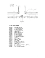
Suspend hanger with #10 Jack chain with strict adherence to specified placement
of hangers, see illustration on page 13. The first hanger must not be more than 6
inches from the burner flange. Hangers have 2 suspension rings. Use top ring if
reflectors are to be horizontal, or side ring if reflectors are to be angled.
2.
With hangers installed, the primary tube can now be placed in the hangers.
Subsequent lengths of tube can now be installed, joining the lengths of tube
together and securing joints with the self-tapping screws provided. The self-
tapping screw holes must be adequately sealed during installation using a high
temperature sealant.
3.
Reflector panels can now be placed in hanging supports. Sheet metal screws may
be used to secure reflectors together in pairs only.
4.
With all radiant tubes and reflector panels now installed, the burner can be fitted
to the 2-flanged primary tubes using the bolted flange and nuts (provided). The
burner must be installed with the fan on the top. Burner employs a ring to
connect a hanging chain to stabilize the unit.
5.
Heaters incorporating baffles must have the baffle installed at the immediate vent
end of the heater. This baffle is not to be installed in the primary tube.
U-SHAPED
HEATER
1.
U-Shaped heaters consist of radiant tubes, “U” bends, hangers, burner and
wide-angle reflectors.
2.
Use #10 Jack chain to suspend the hangers from the ceiling, these hangers
must be spaced according to hanger location illustration.
3.
With hangers now suspended, carefully lay the radiant tube in the holders,
flange section first.
4.
Connect radiant tubes together using the self-tapping screws provided. The
self tapping screw holes must be adequately sealed during installation using a
high temperature sealant.
5.
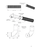
The 180 degree bend can now be fitted to the radiant tube and securely
tightened with self tapping screws provided on 180 degree bend.
6.
Reflectors can now be placed in hangers.
7.
Fit the burner to the flanged end of the tubes with bolts provided and connect
to the gas supply.
If the radiant tube has been supplied in 10ft. lengths, see diagram below for joining tubes
together.
Self tapping screws are provided to be installed into the expanded end of the radiant tube.
Slide the tubes together making sure that the first tube is inserted all the way into the
expanded end of the secondary tube.
Drill the self-tapping screws so as to secure the two tubes together.
Make sure to secure the tubes using the 3 screws provided as indicated in the drawing
below.
Summary of Contents for Middleman EZM-100-50
Page 17: ...17 VENTING OPTIONS...
Page 19: ...19...
Page 20: ...20...
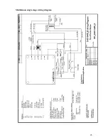
Page 25: ...25 Middleman single stage wiring diagram...
Page 26: ...26 Middleman LTH dual input wiring diagram...
Page 28: ...28...


