16
12.
Horizontal vent systems shall slope downwards not less than ¼” per foot from the
start of the vent system to the vent terminal.
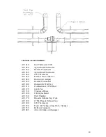
Two units may be exhausted on a common 6” vent with the use of the AC1120
4” x 4” x 6” exhaust T, for both side wall and roof venting. A suitably rated and
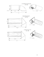
certified high temperature exhaust cap must be used on the end of the 6” exhaust
vent. Units with common exhaust must be jointly controlled. The addition of the
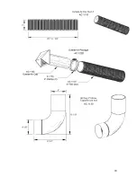
AC1120 exhaust T introduces a 90’ degree bend into the venting of each unit,
deducting 5’ (1.5m) from the allowable total of exhaust/intake venting for each
unit.
WARNING
This heater will expand in length as it heats up. It is a normal condition that during
heat-up and cool-down a tube heater will expand and contract. Allowances for heater
expansion must be made in the gas connection, venting and combustion air ducting.
Improper installation, alteration, or adjustment can result in property damage, injury
or death.
The BTU input and the tube length determine the overall expansion that occurs. A
typical infrared tube installation will expand toward both the burner and the vent end.
To allow heater expansion the gas supply must be installed using:
In the USA: a stainless steel flexible gas connector certified for use on an infrared
radiant tube heater (ANSI Z21.24 CSA 6.10)
In Canada: a Type 1 hose connector (CAN/CGA 8.1). Also the flue vent, and
combustion air intake (if used) must be installed in such a manner that the normal
expansion of the heater will be accommodated.
Summary of Contents for Middleman EZM-100-50
Page 17: ...17 VENTING OPTIONS...
Page 19: ...19...
Page 20: ...20...
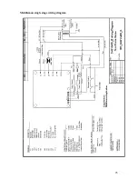
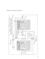
Page 25: ...25 Middleman single stage wiring diagram...
Page 26: ...26 Middleman LTH dual input wiring diagram...
Page 28: ...28...


