background image


7


WARNING 

GAS CONNECTION 

Improper installation, connection, or adjustment can result in property damages, toxic 
gases, asphyxiation, injury and death. Using an approved flexible gas connector in the 
USA and Rubber Type 1 hose connector in Canada, the gas supply to the heater must be 
connected and tested in accordance with all local, state, provincial, and national codes 
(ANSI Z223.1/NFPA 54 in USA: B149.1 in Canada) and as indicated in the manual. 


WARNING 

VENTING 

Inadequate venting of a heater may result in asphyxiation, carbon monoxide poisoning, 
injury or death. The heater may be directly or indirectly vented from the space. Venting 
must be in accordance with all local, state, provincial, and national codes (ANSI 
Z223.1/NFPA 54 in USA; B149.1 in Canada) and as indicated in this manual. 


WARNING 

START-UP SMOKE CONDITION 

During start up, the heating of material coatings used in the production process of tubes 
and reflectors will create smoke during the initial period of operation. This condition is 
normal and temporary.  Ensure that there is sufficient ventilation to adequately clear any 
smoke from the space. Notify site and safety personnel to ensure that alarm systems are 
not unduly activated. 


WARNING 

CLEARANCES TO COMBUSTIBLES 

The stated clearance to combustibles represents a surface temperature of 90 degree 
Fahrenheit (32 degrees Celsius) above room temperature. Building material with a low 
heat tolerance may be subject to degradation of lower temperatures. It is the installer’s 
responsibility to assure that adjacent material are not subject to degradation. 
 
A warning statement that an overhead heater should be installed so that the minimum 
clearances marked on the heater will be maintained from vehicles parked below the 
heater


Location of flammable or explosive objects, liquids or vapours close to the heater may 
cause fire or explosion and result in property damage, injury or death. Do not use, store 
or locate flammable or explosive objects, liquids or vapours in proximity of the heater.  
 
The clearance to combustible material represents the minimum distance that must be 
maintained between the outer heater surface and a nearby surface. The stated clearance to 
combustible represents a surface temperature of  90 degrees F (50 degrees C) above room 
temperature. It is the installer's responsibility to ensure that building materials with a low 

Summary of Contents for Middleman EZM-100-50

Page 1: ...indicates dual input with the low input being 70 of the high input The installation must comply with local codes and CAN CGA B 149 in Canada or the National Fuel Gas codes WARNING Improper installatio...

Page 2: ...If your gas supplier is not available call the fire department 5 Si votre fournisseur de gaz n est pas disponible appeler les pompiers 6 Do not attempt to light this or any other appliance 6 Ne pas te...

Page 3: ...ures It is the installer s responsibility to assure that adjacent material are not subject to degradation A warning statement that an overhead heater should be installed so that the minimum clearances...

Page 4: ...x 50 000 4 13 15 31 EZUM 100 30 oal 32 3 60 ft 100 000 2 x 50 000 EZUM 120 30 oal 32 3 60 ft 120 000 2 x 60 000 Model No Overall Length Radiant Tube Length Input Clearances to Combustibles cm Top Sid...

Page 5: ...E TO COMPLY WITH THESE WARNINGS AND INSTRUCTIONS AND THOSE ON THE HEATER COULD RESULT IN PERSONAL INJURY DEATH FIRE ASPHYXIATION AND OR PROPERTY DAMAGE DO NOT STORE OR USE GASOLINE OR OTHER FLAMMABLE...

Page 6: ...res In case of discrepancy the latest codes standards and installation manual will take priority over prior releases WARNING Where there is the possibility of exposure to combustible airborne material...

Page 7: ...ear any smoke from the space Notify site and safety personnel to ensure that alarm systems are not unduly activated WARNING CLEARANCES TO COMBUSTIBLES The stated clearance to combustibles represents a...

Page 8: ...RIZONTAL HORIZONTALE 30 DEG ANGLE Above Sommet Below Dessous Side Cote Back Dos LABOUR REQUIREMENTS Two persons are required to safely install this equipment Wear gloves and other required safety prot...

Page 9: ...s information in these installation instructions GENERAL INSTALLATION PROCEDURE PRE INSTALLATION SURVEY It is recommended that a full heating design including a heat loss calculation be conducted Heat...

Page 10: ...The burner must be installed with the fan on the top Burner employs a ring to connect a hanging chain to stabilize the unit 5 Heaters incorporating baffles must have the baffle installed at the immedi...

Page 11: ...1 Subsequent secondary tubes can now be joined together in the same fashion The self tapping screw holes must be adequately sealed during installation using a high temperature sealant HANGER LOCATIONS...

Page 12: ...firing rate the greater the expansion Survey the available structural supports considering the system configuration and heat requirements of the area to establish the optimum heater location Locating...

Page 13: ...h flexible gas connector 3 A drip leg must be installed in the gas line at the heater inlet connection tee followed by a pipe drop to the heater Failure to provide a drip leg could result in condensat...

Page 14: ...Type 1 Hose Gas Connector CAN CGA 8 1 The heater must be isolated from the gas supply piping system by closing its individual manual shut off valve field supplied during any pressure testing of the ga...

Page 15: ...ed for that portion of the vent that passed through the wall or roof For wall venting the manufacturer s approved vent spout or exhaust cap must be used See page 20 All models vented through a side wa...

Page 16: ...up It is a normal condition that during heat up and cool down a tube heater will expand and contract Allowances for heater expansion must be made in the gas connection venting and combustion air ducti...

Page 17: ...17 VENTING OPTIONS...

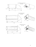
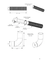
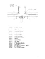
Page 18: ...AC1080 Outside Air Adapter AC1030 Remote Thermostat AC1100 Outside Air Wall Cap AC1110 Combustion Air Flex Duct AC1120 4x4x6 Tee AC1130 90 degree Elbow AC1140 180 degree Bend AC1150 Wall Thimble AC11...

Page 19: ...19...

Page 20: ...20...

Page 21: ...is removed from the igniter The flame sensor is utilized As long as a flame is present the valve is held open If the flame is lost the control acts to close the valve within one second and a new trial...

Page 22: ...alve should be replaced Continued lockout of the control may indicate that the sensor is not providing the signal back to the control flame sensing circuit If the sensor is in the proper position and...

Page 23: ...products for certain purposes which may vary among jurisdictions While Easy Radiant Works attempts to assure that its products comply with these many codes it cannot guarantee compliance or cannot be...

Page 24: ...ompleted reports can be faxed to Technical Support Easy Radiant Works at fax no 905 899 2262 or call phone no 905 899 3473 During startup material coatings used in the production of tubes and reflecto...

Page 25: ...25 Middleman single stage wiring diagram...

Page 26: ...26 Middleman LTH dual input wiring diagram...

Page 27: ...INLET GAS SUPPLY PRESSURE WITH HEATER OPERATING WC GAS VALVE OUTLET Manifold PRESSURE WITH HEATER OPERATING WC WHAT IS THE LINE VOLTAGE READING AT THE HEATER VOLTS WHAT IS THE VOLTAGE READING AT THE I...

Page 28: ...28...
Reviews: