background image

ERP12R/S &


ERP16R/S

3

RAID System Components

Front View

RAID System

JBOD

Open Front Panel

2U12bays

3U16bays

No

Discription

1

LCD / Button Panel

2

Key Lock

No

Discription

1-12

Hard Disk Tray 1-12

No

Discription

1-16

Hard Disk Tray 1-16

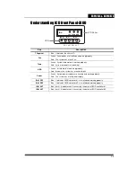
1

2

Power

ID#

IO#1

Fan Temp HDD

RDY ACT RDY ACT

IO#2

1

2

1

2

3

4

5

6

7

8

9

10 11 12

1 2 3 4

5 6 7 8

9 10 11 12

13 14 15 16

Summary of Contents for ERP12R-8FR2

Page 1: ...easyRAID P12R S P16R S Quick Installation Guide 42 30000 5197 Fibre to SAS iSCSI to SAS SAS to SAS JBOD Disk Array Systems Version 1 1...

Page 2: ......

Page 3: ...SAS JBOD Disk Array Systems Model ERP12R 8FR2 ERP12S 8FR2 ERP12R 10GR2 ERP12S 10GR2 ERP12R 6SR2 ERP12S 6SR2 ERP16R 8FR2 ERP16S 8FR2 ERP16R 10GR2 ERP16S 10GR2 ERP16R 6SR2 ERP16S 6SR2 ERP16JS 6SR3 ERP16...

Page 4: ......

Page 5: ...Interface 5 Mounting The RAID System Installing the Slide Rail 6 Installing the Rail Extender 7 Installing Hard Disk Installing The SAS Disk 8 Installing The SATA Disk 8 Configure RAID System By GUI S...

Page 6: ......

Page 7: ...rotect the RAID system from being dropped or mishandled Ensure that the RAID system voltage corresponds to the supply voltage If an extension cord or power center is used with the RAID system make sur...

Page 8: ...e with the maximum ambient temperature specified by the manufacturer 6 Reduced Air Flow Installation of the equipment in a rack should be such that the amount of air flow required for safe operation o...

Page 9: ...s in the box Item qty Disk Box Hard Disk Tray 12 16 pcs 1 RAID System Box Disk Array Syatem 1 pcs Accessary Box Quick Installation Guide 1 pcs Rail 1 set Rail Extender 1 set Front Panel Key 2 pcs 1 Di...

Page 10: ...3 packs for 3U 16bays 4 1 piece for single controller model 2 pieces for redundant controller model 5 For 2U RAID system only Item qty Accessary Box Power Cable 2 pcs 2 Screw pack 2 3 packs 3 x4 SAS C...

Page 11: ...Front Panel 2U12bays 3U16bays No Discription 1 LCD Button Panel 2 Key Lock No Discription 1 12 Hard Disk Tray 1 12 No Discription 1 16 Hard Disk Tray 1 16 1 2 Power ID IO 1 Fan Temp HDD RDY ACT RDY AC...

Page 12: ...iption 1 Hot Swap Power Module 2 Hot Swap FAN Cache Guard Module 3 Hot Swap Controller A B 4 Power Switch 5 UPS Monitor Port Caution DO NOT attempt to remove any component from the FAN CacheGuard modu...

Page 13: ...Port SFF 8088 5 Terminal Port 6 Heart Beat Indicator No Description No Description 1 8Gb Fibre Channel Port 10Gb iSCSI Channel Ports 2 1Gb iSCSI Channel Port RJ45 3 LAN Port RJ45 4 SAS Expansion Port...

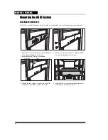
Page 14: ...4 screws making sure that correspond with the mounting points on the rails 2 Adjust the length of the rails as needed 3 Secure the rails using two nuts and bolts on both the front and back posts of th...

Page 15: ...se follow the procedures below to install the rail extenders Follow the procedures below to install the rail extenders Without Rail Extender Installed Raid Extender 1 Install the rail extenders and at...

Page 16: ...talling the SATA Disk SATA hard drive installation requires an AA MUX adapter which have to be installed on the hard disk tray before installing the SATA hard disk follow the procedure below Note Reco...

Page 17: ...I console as below Follow the procedure to quick setup RAID system 1 Login as admin user Default user name is admin password is 0000 2 In menu Quick Setup select member disks and data security option...

Page 18: ...obal Spare F Foreign Conflict disk W SMART warning or BBR alert G Global spare disk X No disk J JBOD mode Unreadable status Color Description Green Power on Red Any event alert from the RAID system Am...

Page 19: ...d It shows the system has a fault hard disk Power Green System power supplies are installed and working properly Red This system has a fault power supply IO 1 RDY Blue It indicates JBOD controller 1 i...

Reviews: