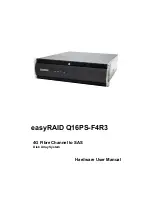
background image

2

easyRAID Q16PS-F4R3

 SAS Disk Array Systems

 Syste

m

 Re
quir
e

m

ents –


VT100 Terminal Settings

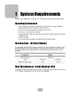
Refer to the following table for a summary of VT100 terminal settings required to com-
municate with the disk array system. Refer to your system manual for instructions on 
setting up the VT100 terminal settings.

Ethernet settings

easyRAID Q16PS-F4R3 supports DHCP (Dynamic Host Configuration Protocol) to get a 
IP address or a default IP is 192.168.0.1; You could find it from LCD scrolling. easyRAID 
Q16PS-F4R3 had embedded CGI-based GUI (graphic user interface) management 
interface can be easily accessed through a web browser.

Item

Required Setting

Connection

 Serial Port (COM1 or COM2)

Protocol

 RS232 (Asynchronous)

Cabling

 Null Modem cable

Baud Rate

 115200

Data Bits

 8

Stop Bit

 1

Parity

 None

Summary of Contents for Q16PS-F4R3

Page 1: ...easyRAID Q16PS F4R3 Hardware User Manual 4G Fibre Channel to SAS Disk Array System Version 1 0 ...

Page 2: ......

Page 3: ...easyRAID Q16PS F4R3 4G Fibre Channel to SAS Disk Array System Hardware User Manual ...

Page 4: ......

Page 5: ...d Front Panel 4 Open Front Panel 5 Disk Tray 6 easyRAID Q16PS F4R3 Rear View 7 Installing Disks 8 Making Connections 10 Connecting the Host Interface 10 Connecting the GUI management port 11 Connecting the JBOD enclosure 11 Connecting and Turning on the Power 12 Mounting in a Rack 13 Installing the Rail Extenders 14 Chapter 3 Maintenance Replacing a Disk 15 Replacing a Power Supply 16 Upgrading Me...

Page 6: ......

Page 7: ...tion are protected by copyright and are distributed under licenses restricting their use copying and distribu tion No part of this documentation may be reproduced in any form by any means with out prior written authorization the company and its licensors if any Conventions Caution This symbol is used to remind users to pay attention to important descriptions regarding usage and maintenance repair ...

Page 8: ...isk array system on an unstable cart stand or table It may fall causing serious damage to the product Keep the disk array system away from magnetic forces Do not use the disk array system near water Keep the disk array system away from dust sand or dirt Gaps and openings in the cabinet are provided for venti lation Never block or cover these openings because the disk array system may overheat and ...

Page 9: ...nd openings since they may touch dangerous voltage points and cause a risk of fire or electric shock Unplug the power cord from the wall outlet before clean ing Keep the disk array system dry Do not use liquid cleaners aerosol cleaners or a wet cloth Use a damp cloth for cleaning Except as specifically explained in this User Manual do not attempt to service the disk array system by yourself Openin...

Page 10: ... To reduce the possibility of data errors caused by electromagnetic interference locate the disk array system at least five feet away from electrical appliances and equipment that generates magnetic fields Power Supply Safety Notes To avoid electric shocks do not use an extended power cord or an outlet that does not match the disk array system plug or leaves the plug exposed The disk array system ...

Page 11: ...ect sunlight a flat stable surface capable of supporting the disk array system Host Interface 4G Fibre Channel The easyRAID Q16PS F4R3 has dual 4 Gbit fibre channel interfaces with SFP connec tors for linkage to a fibre channel switch or host computer interface card With the cor rect SFP transceiver and optical cable the following transmission distances can be achieved Hard Disk Interface Serial A...

Page 12: ...inal settings Ethernet settings easyRAID Q16PS F4R3 supports DHCP Dynamic Host Configuration Protocol to get a IP address or a default IP is 192 168 0 1 You could find it from LCD scrolling easyRAID Q16PS F4R3 had embedded CGI based GUI graphic user interface management interface can be easily accessed through a web browser Item Required Setting Connection Serial Port COM1 or COM2 Protocol RS232 A...

Page 13: ...ed Caution The disk array system is heavy Be careful when lifting and moving it Power P S Fail Access Enter ESC Power P S FailAccess Enter ESC Pri Sec Power P S FailAccess Enter ESC Pri Sec Power Cables Front Panel Keys Hardware and software user Manuals Disk Array System RS 232 Cable HDD Screw pack Rails Rail Extenders Fix Screw pack M5 Fix Screw pack UNC 10 32 Fix Screw pack M6 ...

Page 14: ...l indicator Indicates a failed power supply 4 Host computer access indicator Indicates data transfer between the disk array sys tem and the host computer 5 Up function button Moves up in the LCD menus 6 Down function button Moves down in the LCD menus 7 Enter function button Selects a menu item or confirms a choice or entry 8 Escape function button Returns to the previous LCD menu without making c...

Page 15: ... 1 16 Removable hot swap disk trays 17 Front panel door Protects the disks and houses the LCD panel Disk1 Disk2 Disk3 Disk4 Disk5 Disk6 Disk7 Disk8 Disk9 Disk10 Disk11 Disk12 Disk13 Disk14 Disk15 Disk16 Disk Mapping Color Status Bule Access Green Disk Online Red No Disk Tray LED Indication 1 2 3 4 5 6 7 8 9 10 11 12 13 14 15 16 17 ...

Page 16: ...Disk Tray No Name Description 1 Power Error indicator LED Different colors indicate different disk states Green Disk online Orange Disk fail Red No disk 2 Access indicator LED This blue LED indicates that the disk is being accessed 3 Tray handle Releases the disk tray 2 1 Front 3 ...

Page 17: ...inal or equivalent 5 UPS port Data port for uninterruptable power supply 6 Cooling fan 2 System cooling fan 7 Power Supply 2 Removable redundant power supply 2 8 Power Supply Handle For power supply removal 9 Power Supply AC In Connects to a 100 240 VAC power source 10 Power Supply Switch Switches the power on or off 11 Ethernet Port Used for browser based configuration 12 Expansion Port Used for ...

Page 18: ...he button A to release the disk tray handle Pull the handle B to release the tray 3 Align the rear of the disk with the rear of the disk tray 4 Insert the disk into the disk tray and fix into place with screws supplied with the disk Disk1 Disk2 Disk3 Disk4 Disk5 Disk6 Disk7 Disk8 Disk9 Disk10 Disk11 Disk12 Disk13 Disk14 Disk15 Disk16 Disk Mapping Color Status Bule Access Green Disk Online Red No D...

Page 19: ...e front panel door closed and lock it Note If you are combining SAS and SATA in the same easyRAID Q16PS F4R3 Recommending DO NOT include SAS and SATA disks in the same column A or DO NOT place a column of SATA disks between two columns of SAS disks B A B Disk1 Disk2 Disk3 Disk4 Disk5 Disk6 Disk7 Disk8 Disk9 Disk10 Disk11 Disk12 Disk13 Disk14 Disk15 Disk16 Disk Mapping Color Status Bule Access Gree...

Page 20: ...k array system has dual fibre channel interfaces Refer to the following sections to make host interface connections The easyRAID Q16PS F4R3 has dual 4 Gbit fibre channel interfaces Each interface can be used with optical or copper transceivers and cables Follow these instructions to make optical connections 1 Insert the LC Optical SFP transceiver A in to the easyRAID Q16PS F4R3 FC CH 2 secondary f...

Page 21: ...I management port by a Ethernet cable standard RJ45 to LAN WAN environment and open a web browser with easyRAID Q16PS F4R3 IP address Default is 192 168 0 1 and DHCP exabled for easily monitoring configuring RAID sys tem Connecting the JBOD enclosure Connect a SAS SFF 8088 miniSAS connector external cable to JBOD enclosure COM UPS COM UPS ...

Page 22: ...ning on the Power 1 Plug a power cable A to a power connector at the rear of the unit then plug the second power supply cable into the second power connector B 2 Switch on both power supply switch C Note The system is equipped with auto switching power supplies that can run on 100 to 240 VAC COM UPS A B C ...

Page 23: ...mounting points on the rails 2 Extend both of the rails so that they are the right length to fit in your rack 3 Bolt the rails into the rack using the rack bolts supplied with your rack You will need four nuts and bolts not included for each rail two at the front and two at the back 4 Tighten the locking screws when they are the correct length 5 Slide the disk array system into the rack and bolt i...

Page 24: ...ns to fit the rail extenders if required 1 If required bolt the rail extenders into place as shown using the small bolts pro vided 2 Slide the disk array system into the rack and bolt it into place with the supplied fixing screws Note The rail extenders may be required to allow the disk array system room for the front door to open correctly ...

Page 25: ... the disk tray 4 Align the rear of the new disk with the rear of the disk tray 5 Insert the new disk into the disk tray 6 Attach the disk to the disk tray with the screws that came with the disk 7 Slide the disk tray back into the empty slot then close the disk tray handle 8 Push the front panel door closed and lock it Note Turn off the audible alert by pressing the Up and Down function but tons o...

Page 26: ...the disk array is powered on and operating Follow these instructions to replace a failed power supply 1 Identify the power supply that has failed 2 Remove the power cable from the power supply connector at the rear of the unit 3 Loosen the power supply retaining screw 4 Remove the faulty power supply by pulling the power supply handle A and pressing the release catch B at the same time 5 Insert a ...

Page 27: ... in place slide the controller cage out of the chassis 2 Pull the DIMM retaining clips away from the DIMM the DIMM springs out of the socket Remove the DIMM 3 Gently push the new DIMM into the socket then push the corners of the DIMM down The DIMM is secured by the DIMM retaining clips Push the controller cage back in lower the handle and tighten the retaining screws Note The DIMM module will fit ...

Page 28: ...ears on the LCD panel where x refers to power supply 1 or 2 and an audible alert sounds 1 Identify the FAN module that has failed loosen the retaining screws slide it out of chassis 2 Insert a new FAN module tighten retaining screws Note Turn off the audible alert by pressing the Up and Down function buttons on the front panel twice simultaneously COM UPS COM UPS ...

Page 29: ...thout disks Management IO connector 1 x RS 232 COM port 1 x RJ 45 LAN port 10 100 Mbps JBOD Expansion Yes optional Battery Backup Module Yes optional FAN Turbine FAN x 2 Hot Swapable Power Supply Redundant 1 1 460 Watt 100 240 VAC 47 63 Hz 6 3A 10 Over voltage current power and short circuit protection LED indicates power status Output 5V 3 3V 12V Operating Enviroment Temperature 5 C 40 C Humidity...

Page 30: ......

Reviews: