5
MN-662
EasyStreet
PREPARING REAR BAG ASSEMBLY
Refer to fi g. 1 on page 3 for detailed assembly.
1. Installed supplied air fi tting (M) into air bag assembly before attaching the upper bracket
(B).
2. Insert the roll plate (N) to the bottom of the air spring assembly.
3. Attach lower mounting plate using supplied 3/8”-24 x 3/4” countersink cap screw.
4. Using supplied 3/8”-24 x 3/4” hex bolts, lock washers, and fl at washers, attach the upper
bracket tube assembly. Torque the bolts to 20 ft/lbs.
5. Insert the 3/8’ - 16 x 1½” countersink cap screw into the lower mounting plate before
installing the bag assembly.
6. Upper bracket window faces the rear of the vehicle.
INSTALLING BAG ASSEMBLY
Driver’s side installation shown.
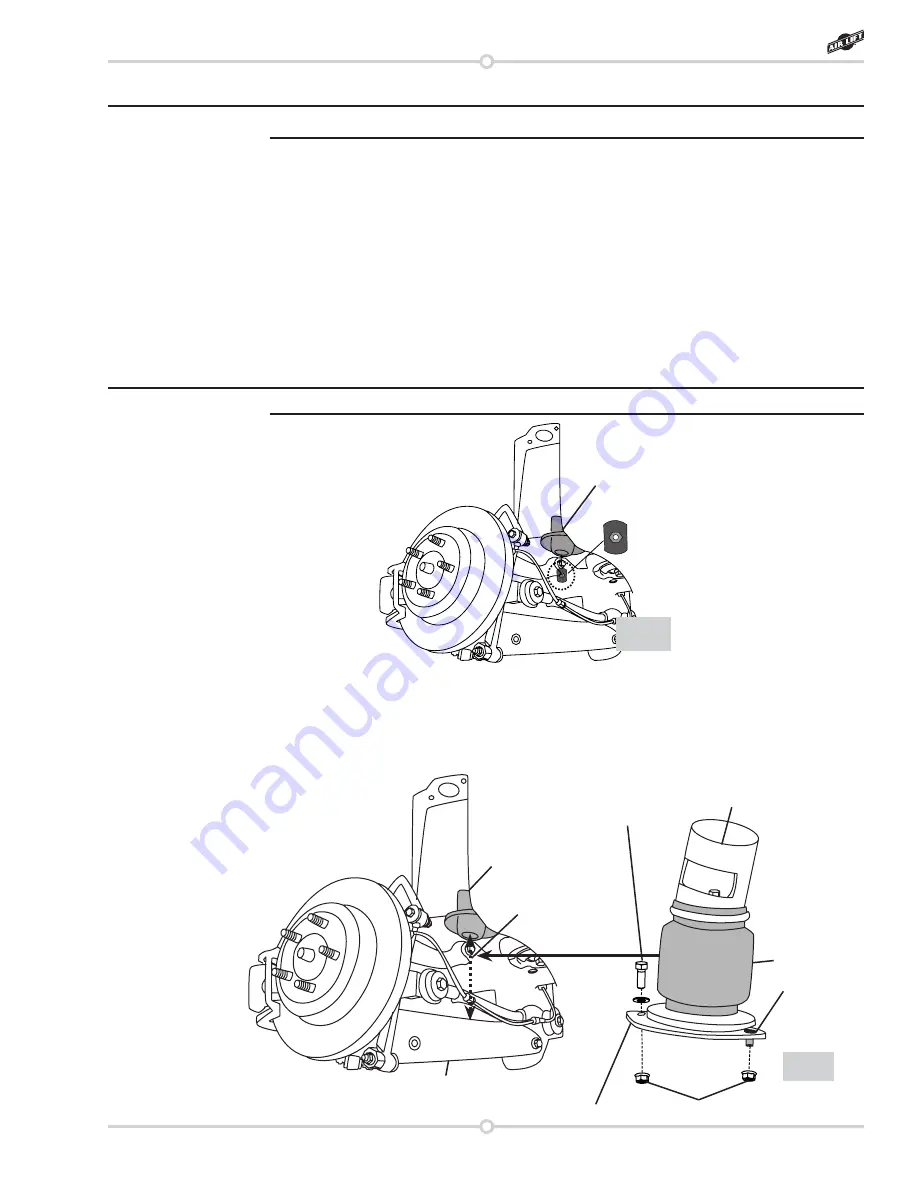
1. Insert clamp plate into spring retainer boss with the nut facing upward (fi g. 4).
2. Collapse assembly and slide into stock coil spring location.
3. Insert and snug nuts and bolts into existing holes required for lower control arm (fi g. 5).
4. Use a jack to raise spindle so the upper bracket tube assembly locates in the upper
spring pocket.
Clamp plate
Spring Retainer Boss
fi g. 4
NOTE
NOTE
fi g. 5
Bag Assembly
Lower Mounting Plate
Stock Coil Spring
Location
Lower Control Arm
3/8”-16 x 1” Bolt and Washer
Spring Retainer Boss
(not visible;
inserted into
the clamp plate
previously
installed in fi g. 4)
3/8”-16 x 1½”
Countersink
Cap Screw
3/8”-16 x 1” Nut
Bolt & 3/8” Flat
Washer
3/8” Flange Nut
Summary of Contents for AIR LIFT 75695
Page 2: ...2 MN 662 EasyStreet ...
Page 11: ......


