6
MN-662
EasyStreet
Technician’s Signature ___________________________
Date ______________
Have all fasteners been torqued to specification (20 ft/lbs)?
Is there adequate clearance around all link arms and stabilizer bars (1/2”
minimimum inflated at 80 p.s.i.)?
Has the the system been checked for leaks?
Are all air lines routed correctly and away from heat sources (3”
minimum)?
Is a copy of the installation instructions in the vehicle for the customer?
Before Operating
INSTALLATION CHECKLIST
5. Insert supplied 3/8”-16 x 1” bolt and washer into upper mount clamp plate until fi nger tight
(fi g. 5).
6. Insert bolts into lower mounting plate (fi g.5).
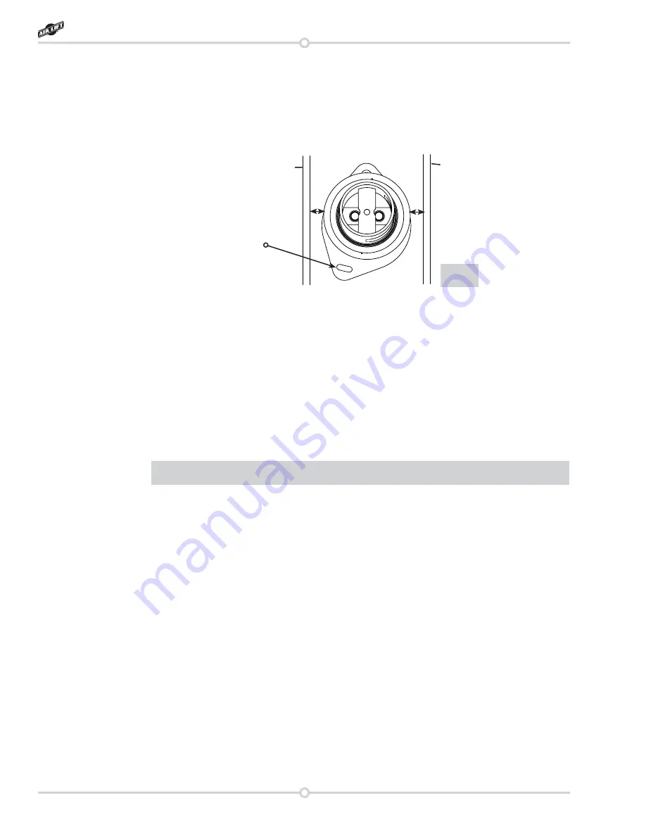
7. Rotate the bag assembly and lower mounting plate for proper bag alignment. There should
be ½” clearance between the completed assembly and the drive shaft and rear stabilizer
bar. Window in upper bracket tube assembly faces the rear of the vehicle (fi g. 6).
8. Infl ate assembly to 40 p.s.i. and check for leaks and clearance between all drive train
and control arms.
9. Defl ate the assembly, making adjustments as needed.
10. Tighten all fasteners to 20 ft/lbs.
11. Reinstall the shock with original upper retaining bolts and the lower shock bolt, nut and
washer.
12. Repeat steps 1-11 on the other side of the vehicle.
fi g. 6
Top-down View
Drive Shaft
Rear Stabilizer Bar
Rotate the lower
mounting plate to
achieve proper
bag alignment.
½”
½”
Summary of Contents for AIR LIFT 75695
Page 2: ...2 MN 662 EasyStreet ...
Page 11: ......


