5
5HP INLINE PUMP MANUAL REV030921
2.
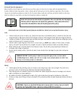
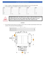
Connect main feed line to check valve. Pump
MUST
have a check valve installed inline to tank. This helps to
prevent the pump from starting underload. This also prevents air loss and premature pump wear. Minimum line
ID size for main line
is 5/8”. This can
be flexible or solid.
DO NOT
install the unit with a shut off valve anywhere
in the main feed line. This could lead to serious injury or death.
Output threads are ¾” FNPT.
3.
Pressure lubed pumps
DO NOT
have built in unloaders and require a separate relief valve. This will relieve head
pressure once the pump stops and provide no-load restarting.
4.
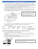
Cylinder heads are equipped with continuous run lines. If the lines are not to be used, please cap input side.
Lines on the head are for input from a manufacturer approved pilot valve only.
DO NOT
run lines from relief
valve or unregulated lines from the tank to this system.
5.
Use proper pulley for motor size and RPM.
DO NOT
exceed pump maximum recommended RPM. Exceeding
pump RPM will cause premature wear/damage to the pump and will void pump warranty.
6.
Pulley calculation worksheet:
Pump
Flywheel OD Pump RPM
min
Pump RPM
max
Motor RPM
Suggested Size*
APP2I0543TP
16.75
450
800
Per Application
Flywheel
x
Pump RPM
/
Motor RPM
=
Pulley OD
*EXAMPLE: 16.75
” x 8
00 (pump RPM) / 1750 (example) motor RPM = suggested pulley size of 7.7
”
7.
This model
of pump requires the use of two, ‘B’ groove belts.
8.
Rotation of the pump should be clockwise when facing the pressure gauge, or counterclockwise from the
flywheel side.
9.
Use care when aligning pump flywheel and motor pulley. Ensure center ridge on pump and pulley are in line.
Any direction out of line will cause premature belt wear.
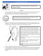
10.
When tightening belts check for belt deflection. Deflection should be no more than ½ inch.
Input lines for continuous run set up only.
DO
NOT
run lines from other sources to these
locations. Use only a manufacturer approved
pilot valve for continuous run use.
Proper belt tension is determined by pressing midway between the
motor pulley and the pump flywheel.
Summary of Contents for 5HP
Page 1: ...APP2I0524TP 5HP INLINE PUMP MANUAL REV030921...
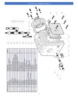
Page 10: ...9 5HP INLINE PUMP MANUAL REV030921 Pump Explosion Parts List...
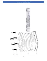
Page 11: ...10 5HP INLINE PUMP MANUAL REV030921...
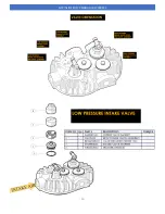
Page 12: ...11 5HP INLINE PUMP MANUAL REV030921...
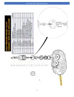
Page 13: ...12 5HP INLINE PUMP MANUAL REV030921...
Page 14: ...13 5HP INLINE PUMP MANUAL REV030921...
Page 15: ...14 5HP INLINE PUMP MANUAL REV030921...
Page 16: ...15 5HP INLINE PUMP MANUAL REV030921...
Page 17: ...16 5HP INLINE PUMP MANUAL REV030921...
Page 18: ...17 5HP INLINE PUMP MANUAL REV030921...

