Polar Compressor Rotary Screw Compressors
Revision July.2015
www.eatoncompressor .com
877.283.7614
8 |
P a g e
Piping
Safety Steps
1.
Install appropriate flow-limiting
valves as necessary, according to
pipe size(s) and run lengths. This
reduces pressure in case of hose
failure, per OSHA Standard 29 CFR
1926.302(b)(7).
2.
Flow-limiting valves are listed by
pipe size and rated CFM. Select
appropriate valves accordingly, in
accordance with the manufacturer’s
recommendations.
3.
Do not install check valve as
compressor has internal check valve.
Installing
1.
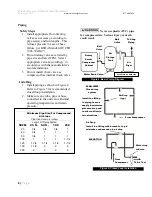
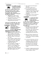
Install piping as shown in Figure 4.
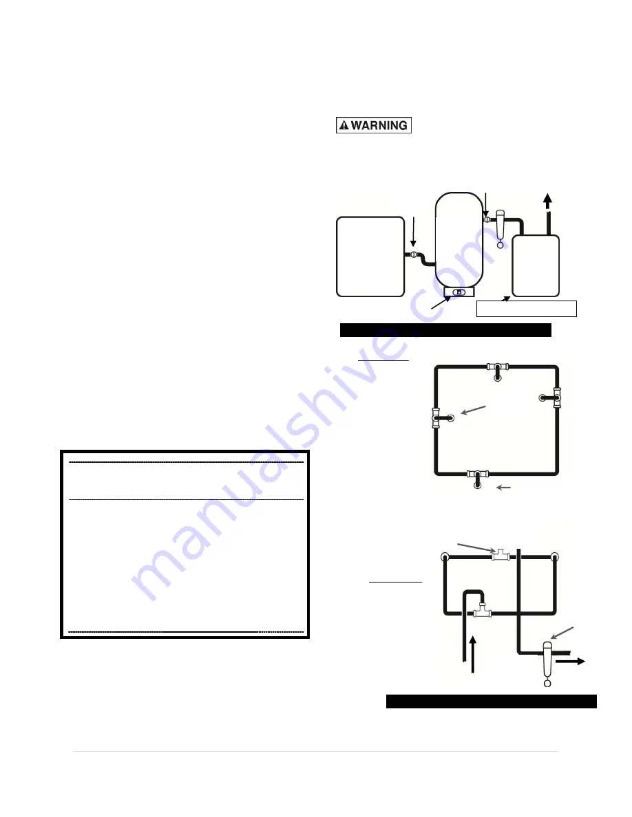
Refer to Figure 5 for recommended,
closed loop installation.
2.
Make sure any tube, pipe or hose
connected to the unit can withstand
operating temperatures and retain
pressure.
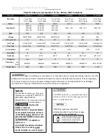
Minimum Pipe Size For Compressed
Air Lines
Pipe Size Shown in inches)
Length Of Piping System
SCFM
25 ft. 50 ft.
100
ft.
250
ft.
20
3/4
3/4
3/4
1
40
3/4
1
1
1
60
3/4
1
1
1
100
1
1
1
1-1/4
125
1-1/4
1-1/4
1-1/2
1-1/2
150
1-1/2
2
2
2
200
2
2
2
2
Never use plastic (PVC) pipe
for compressed air. Serious injury or death
could result.
Rotary
Screw
Compressor
Cabinet
Air
Storage
Tank
Air
Dryer
To Shop
Piping
Ball
Valve
Water Drain Valve
Ball
Valve
Figure 4: Basic Piping Diagram
PLAN VIEW
Closed loop
system
Install tee fitting
in piping from air
supply to minimize
pressure drop and
to allow airflow in
two directions.
Air Drop
(typ.)
Air Drop
Install tee fitting with branch to top to
minimize condensation in air drop
ELEVATION
From
Compressor
To Air Tool
Water trap
w/drain
Figure 5: Closed Loop Installation
From Compressor
Auto Drain on back side


