
IOM 2596 Cast 10”–16” | Fabricated 10”-36” 10/2011
REV A.
Page 3 of 15
Eaton Filtration, LLC, 44 Apple Street, Tinton Falls, NJ 07724 | www.eaton.com/filtration | Phone: 732-212-4700
Installation, Operation & Maintenance Manual
Model 2596 Self-Cleaning Strainer
Cast 10” to 16” and Fabricated 10” to 36”
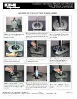
Be sure flange gaskets are in place and fasteners are tight.
Inspect all external components of the operating mechanism
for damage due to handling and shipping. Manually rotate the
backwash arm to observe proper alignment.
To operate manually and determine freedom of movement,
see “Manual Operation of Backwash Arm”, page 6. If backwash
arm rotates freely proceed with installation.
If binding occurs, follow “Removal of Cover and Operating
Mechanism Assembly” procedures contained on page 6 and
rectify cause of binding.
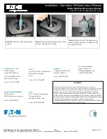
Follow “Reassembly of Cover and Operating Mechanism
Assembly” procedure on page 6. Then proceed with
installation
.
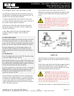
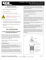
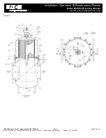
For Fabricated Strainers:
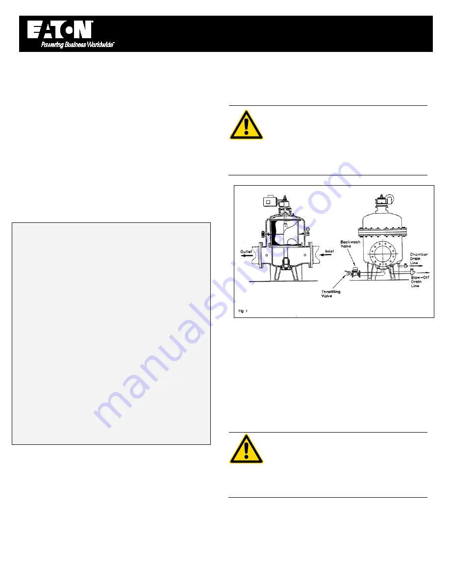
Attach the blow-off/drain line to the NPT coupling in the center
of the bottom head. See Figure 1. Install a ball, gate or plug
valve in this line. Keep this valve closed except when necessary
to drain the strainer or blow-off debris settled on the bottom.
Attach the backwash line to the side flanged opening. It is
important to prevent backpressure by having a short, free
flowing backwash line with no vertical risers and a minimum of
bends.
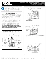
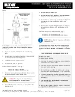
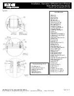
For Cast Strainers:
Attach the chamber drain line to the 1” NPT threaded opening
on the outer edge of the filter. See Fig 1.
Attach the blow-off drain line to the offset 2” NPT opening. See
Fig 1. Install a manually operated ball, gate or plug valve in this
line. Keep this valve closed except when necessary to drain the
strainer or blow off debris settled on the bottom.
Attach the backwash line to the center 2” NPT or 2” 150# ANSI
flanged opening. It is important to prevent back pressure by
having a short, free flowing backwash line with no vertical
risers and a minimum of bends.
Install a backwash control valve in this line. The valve may be
manually or automatically operated. It is recommended that it
be used only for full-on/full-off control except for high pressure
or mesh screen applications in which the backwash control
and/or throttling valve should be adjusted to a flow rate which
attains thorough cleaning only.
Connect power source to the strainer motor. Note: It is
advisable to use flexible power cable with extra length to allow
for strainer cover removal without having to disconnect the
motor.
CAUTION:
Be sure power source matches motor
requirements. Damage may occur if improperly
connected. Motor starter should incorporate a
thermal overload device to protect the motor.
Interlock strainer motor with process fluid service pump where
feasible. Install a fusible disconnect or circuit breaker on the
incoming power service.
START-UP
Check the reducer for lubricant. Fill unit to pipe plug level with
proper oil if level is low. See “Reducer Maintenance” section on
page 5.
Install or open reducer vent which has been plugged to prevent
lubricant loss during shipment. Loosen packing gland nuts.
Energize strainer motor and/or controls. Open vent on strainer
cover. Slowly introduce fluid to be strained.
CAUTION:
The initial start-up should be done
while in the continuous backwash mode. Once the
system has been purged of all initial construction
debris, the automatic mode can be activated. The
thordon bearing is lubricated by liquid to be strained. DO NOT
operate for long periods before strainer is filled with fluid. Do
not over tighten the packing gland nuts.
Close strainer vent when air is expelled and fluid begins to flow.


