
IOM 2596 Cast 10”–16” | Fabricated 10”-36” 10/2011
REV A.
Page 6 of 15
Eaton Filtration, LLC, 44 Apple Street, Tinton Falls, NJ 07724 | www.eaton.com/filtration | Phone: 732-212-4700
Installation, Operation & Maintenance Manual
Model 2596 Self-Cleaning Strainer
Cast 10” to 16” and Fabricated 10” to 36”
MANUAL
OPERATION
OF
BACKWASH
ARM
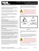
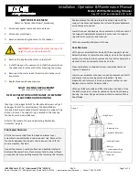
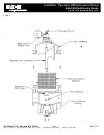
The Model 2596 is furnished with a removable drive key to
facilitate manual operation.
1.
De-energize the power supply to the strainer motor.
Remove the hair cotter pin and tap out drive pin from shaft
(see Fig 2).
2.
Hold shaft flat with adjustable wrench and back off the
lock nut 1/2 turn.
3.
The backwash can now be rotated manually. Manually
open the backwash control valve (manual cleaning only).
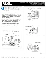
4.
Place a wrench on the flats at the top of the shaft and
rotate the backwash arm at approximately 5 RPM as often
as required to maintain a low pressure drop (manual
cleaning only). One turn minimum for pre-startup.
5.
To return the strainer to normal operation first close the
backwash control valve (manual cleaning only).
6.
Align the cross hole in the B/W shaft with gear reducer by
rotating the drive shaft.
7.
Insert drive pin in B/W arm shaft and secure with hair
cotter pin.
8.
Tighten lock nut.
9.
Energize the power supply to the strainer drive motor.
The strainer is now ready for operation
.
DISASSEMBLY
&
PARTS
REPLACEMENT
PROCEDURES
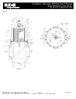
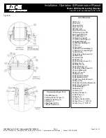
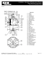
The Model 2596 may be disassembled entirely without removal
from the pipeline to permit examination or replacement of any
individual part. Refer to this manual and the included assembly
drawings for the location of parts.
CAUTION:
Do not perform any maintenance on
this strainer until normal shut down procedures
have been performed.
REMOVAL
OF
COVER
AND
OPERATING
MECHANISM
ASSEMBLY
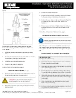
This assembly can be removed as a complete unit. Refer to
“Normal Shut-Down” procedures.
NOTE:
To ensure ease of assembly and avoid
damage to element, all legs of sling must be of
equal length.
1.
Disconnect power source and remove fuses.
2.
Disconnect electrical connections to the motor.
3.
Remove the cover nuts on cast strainers or loosen swing
bolt nuts and swing bolts to clear blocks on fabricated
strainers.
4.
Lift the cover assembly gently, using the cover lifting lugs
on fabricated strainers or the cover lifting eyes on cast
strainers. These lifting lugs/eyes are for the cover
assembly. Note: See “Installation” procedures to lift
strainer.
5.
All internal parts may now be inspected for deterioration,
wear or blockage and replaced or repaired as necessary.
Inspection should include the element and bushing. The
replacement procedures for the reducer, motor and filter
are contained herein.
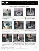
REASSEMBLY
OF
COVER
AND
OPERATING
MECHANISM
ASSEMBLY
Examine cover O-ring seal and replace O-ring if necessary.
Refer to “Replacement or Maintenance of Filter Element on
Page 7.
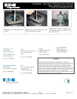
CAUTION:
Do not use excessive force on the
backwash arm. Disconnecting the shaft from the
reducer also disconnects the shaft from the
protection of the motor overloads. If excessive
resistance is met, rotate in the opposite direction to dislodge
any wedged debris. If this does not work, the cover must be
removed and the source of blockage cleared away.


