IOM 2596 Cast 10”–16” | Fabricated 10”-36” 10/2011
REV A.
Page 7 of 15
Eaton Filtration, LLC, 44 Apple Street, Tinton Falls, NJ 07724 | www.eaton.com/filtration | Phone: 732-212-4700
Installation, Operation & Maintenance Manual
Model 2596 Self-Cleaning Strainer
Cast 10” to 16” and Fabricated 10” to 36”
MOTOR
REPLACEMENT
(Refer to “Normal Shut-Down” procedure)
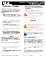
1.
Disconnect power source and remove fuses.
2.
Disconnect motor leads.
3.
Remove bolts holding the motor to the reducer.
CAUTION:
Do not allow the motor to drop, or its
weight to rest, on the output shaft.
4.
Remove the key from the motor output shaft.
5.
Install the key on the new motor, install the new motor on
the reducer and secure with motor mounting cap screws.
6.
Reconnect the motor leads. (Direction of rotation is not
important).
7.
Replace fuses and connect power.
SHAFT
PACKING
REPLACEMENT
(SEE IDL SHAFT SEAL INSTRUCTIONS)
REPLACEMENT
OR
MAINTENANCE
OF
ELEMENT
&
BACKWASH
ARM
BUSHING
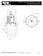
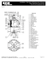
(See Figs 5 & 6, pages 10 & 11 for fabricated strainers or Figs 7
& 8 pages 12 & 13 for cast strainers) The Model 2596 is
furnished with a removable element secured to a support ring
by four roll pins. The support ring is secured to the cover by
four bolts, washers and locknuts.
Refer to “Removal of Cover and Operating Mechanism
Assembly”, page 6.
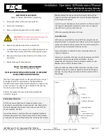
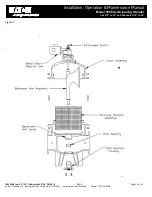
Fabricated Strainers
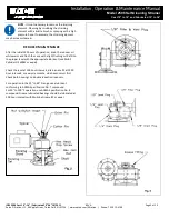
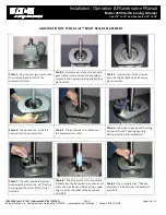
Lift the cover assembly from the body and lower cover
assembly to supports placed under support ring. Remove the
four bolts between the support ring and cover, then lift the
cover assembly. See Fig 4
Inspect the element, sealing surfaces and bushing located at
bottom of backwash arm. Clean element and sealing surfaces
as required. Remove existing element by removing the roll pins.
Replace element by aligning the element tab holes with the
support ring holes and replace the roll pins. Replace backwash
arm bushing as required.
Lower the cover and backwash arm assembly into the center of
the support ring/element assembly. Secure cover to support
ring with bolts, washers, and locknuts.
Lift cover assembly and place into body.
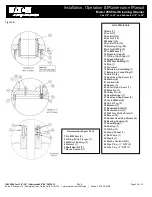
Cast Strainers
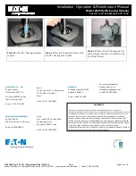
Lift the cover assembly from body. With two supports placed
below the element, lower the assembly as close to the supports
without touching, and then remove the four bolts allowing the
element to rest on support horses. See Fig 4A.
Clean sealing faces in body and cover. Inspect gaskets and
replace if necessary.
Lower cover assembly onto new or existing element until bolts
and elastic stop nut can be fastened together. Tighten
diagonally until element is firmly and evenly seated in cover.
Replace stop nuts after 3 disassembles.
Lift cover, B/W assembly and filter and place into body. Once
the B/W arm guide is properly seated on the bottom bearing
housing, the cover flange will come into full contact with the
body flange.
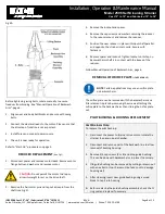
Lifting Device
Cover
Backwash Arm
Hex Bolts & Washers
Straining Element
Hex Nuts & Washers
Lower Support Ring
Roll Pins
Supports
Figure 4


