IOM 2596 Cast 10”–16” | Fabricated 10”-36” 10/2011
REV A.
Page 8 of 15
Eaton Filtration, LLC, 44 Apple Street, Tinton Falls, NJ 07724 | www.eaton.com/filtration | Phone: 732-212-4700
Installation, Operation & Maintenance Manual
Model 2596 Self-Cleaning Strainer
Cast 10” to 16” and Fabricated 10” to 36”
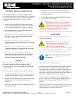
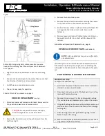
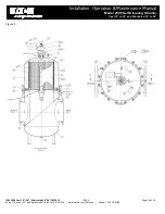
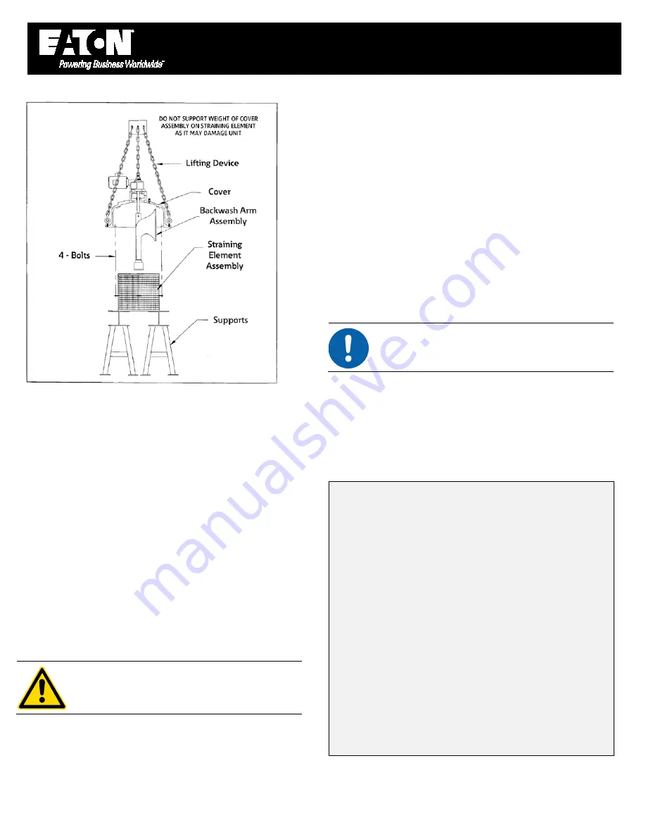
Fig 4A
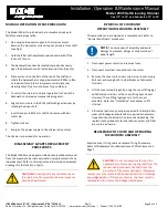
Before tightening swing bolts, rotate manually to ensure
freedom from binding. See “Manual Operation of Backwash
Arm”, page 6.
1.
Align cover and body bolt blocks and secure with swing
bolts.
2.
Connect the electrical leads to the motor. Please note that
the direction of rotation is not important.
3.
Install fuses and connect power source.
4.
The unit is now ready for operation.
Refer to “Start-Up” procedures on page 3.
REDUCER
REPLACEMENT
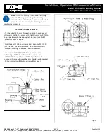
(See Fig 3)
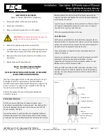
1.
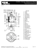
Disconnect power and remove motor leads. Remove motor
flange bolts and washers and remove motor.
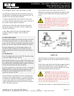
CAUTION:
Do not permit the motor to drop or
allow its weight to rest on the drive shaft.
2.
Remove the hair cotter pin and tap out drive pin from the
shaft (see Fig 2).
3.
Remove the locknut and spacer.
4.
Remove the cap screws and washers securing the reducer
to the reducer mount and remove the reducer.
5.
Position the new reducer in place with input shaft parallel
and opposite the strainer inlet nozzle. Secure with
fasteners.
6.
Replace spacer and locknut. Tighten locknut until step on
backwash arm shaft is in contact with the sleeve of the
reducer.
Follow Manual Operation of Backwash Arm, page 6.
REMOVAL
OF
ORIFICE
PLATE
(IF
APPLICABLE)
NOTE
: Certain applications may use an orifice plate
on backwash arm.
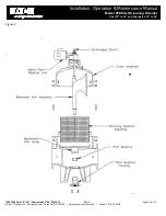
The orifice plate can be removed with the backwash arm and
filter element in place by removing the screws attaching the
orifice plate to the backwash arm then sliding the orifice plate
out.
PILOT
BUSHING
&
HOUSING
REPLACEMENT
Cast Strainers Only:
To replace the pilot bushing:
1.
Disconnect the power to strainer drive motor. Isolate the
strainer then drain inner chamber.
2.
Disconnect and remove part of the backwash line to allow
removal of bushing housing.
3.
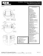
Remove 3/4 cap screws (4 or 8) and drop guide bushing.
This can be done with backwash arm in place if necessary.
4.
Old guide bushing can be removed by cutting or drawn out
with an extractor tool. Care must be taken not to damage
housing wall.
5.
After cleaning, insert new guide bushing using a wood
block to tap it into housing.
6.
Before replacing the guide bushing assembly, check the O-
ring seal and replace if necessary.


