IOM
Controls 04/2020
REV B.
Page
4
of 9
Eaton Filtration LLC,
44 Apple
Street, Tinton Falls,
NJ
07724 www.eaton.com/filtration
Phone:
732-212-4700
Installation, Operation & Maintenance Manual
Control Panels for Automatic Self-Cleaning Strainers
Model 596 and Model 2596
DIFFERENTIAL PRESSURE SWITCHES
SWITCH DESCRIPTION
(SINGLE OR DUAL ELEMENT)
A diaphragm type differential control with single switch is
standard. It initiates a backwash cycle whenever a high
differential pressure drop occurs across the strainer. A dual
element switch is optional where operation requires the first
switch to initiate the backwash cycle. The second switch
activates on further increasing differential pressure and
energizes a visual or audible alarm, calling for operator
assistance.
DIFFERENTIAL PRESSURE SWITCHES
The differential pressure switch easily mounts on the
control panel supports or attached to a bracket that is
welded to the strainer body.
CAUTION:
Never drill into the strainer body
to mount instrumentation or support
brackets.
CAUTION:
Welding brackets to cast iron units
is not recommended and should be avoided.
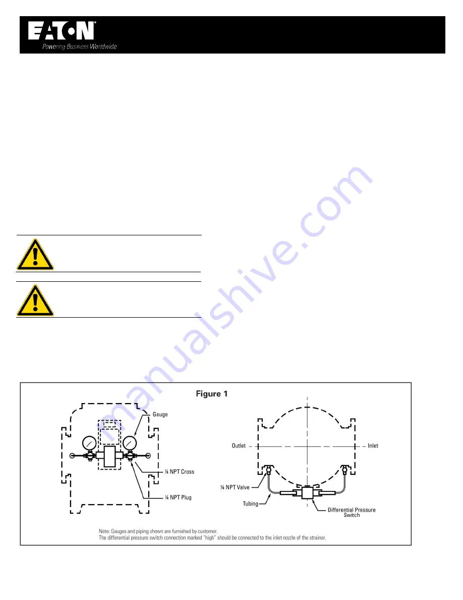
The switch is piped to the pressure connections furnished on
the inlet/discharge nozzles of the strainer as shown in Fig 1.
Customer must supply and run wiring and conduit between the
differential pressure switch and the control panel. See Fig 2 for
wiring connections.
DIFFERENTIAL SWITCH ADJUSTMENT
While it is possible to use other equipment than what is
described below, any installation should have the items
described here.
Equipment to be furnished by customer:
2 calibrated pressure gauges
2 gauge valves with drain
2 tees, tubing, and fittings
All items suitable for
1/4”
NPT connections
Install all equipment as shown in Fig 1. Open the gauge valves
and record the pressure readings at inlet/discharge of strainer
operating at rated flow. The difference in reading is the
“N
orm
al”
pressure drop across the system. Close both gauge
valves. Set switch at
“N
ormal Plus 2 ps
i”
using the adjustment
screw at the calibrated scale. To simulate a high differential
pressure, carefully vent the
“
ou
tlet”
side gauge valve only.
Note the pressure difference at which the switch is
“
activated
.”
Using the adjustment screw on top of the switch, adjust until
switch activates at the proper set point. The
“High”
alarm
setting (optional) should be set at
“N
ormal Plus 4 ps
i.”
Special
applications may require other settings than those given above.
Switch should be re-calibrated at least every 6 months
.


