background image

2

Instruction Leaflet 

IL2C13761H11

Effective March 2020

Installation instructions for Kirk

Key Interlock Kit (2C12891G21) in

Magnum low-voltage circuit breakers

EATON

 www.eaton.com

Section 1: General information

This key interlock provides the following safety features:

1. 

With no key, the breaker is “OPEN” and cannot close.

2. 

With the key “ON”, the breaker is fully functional. 

3. 

The key cannot be removed when the breaker is “ON”. The key 

cannot turn the breaker “OFF”.

ote: 

N

To remove the key, press the breaker “OFF” button, and rotate 

the key 90 degrees counterclockwise.

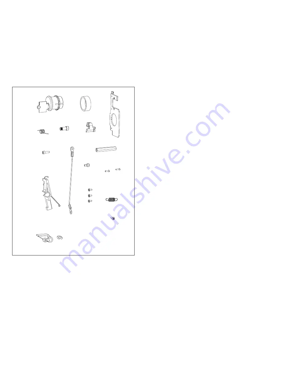
(B)

(A)

(E)

(G)

(F)

(H)

(C)

(D)

(K)

(J)

(N)

(M)

(I)

(L)

(Q)

(O)

Not supplied 

(Kirk–#KC4–10)

(Items O and P not always needed)

(P)

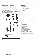
Figure 1. Contents of kit 2C12891G21

Required tools

• 

1/4 inch socket drive

• 

10 mm socket

• 

#2 Phillips head screwdriver

• 

1 7/16 inch (36 mm) hole saw

• 

3/32 hex key

• 

9/64 hex key

• 

Needle nose pliers

• 

Arbor press, bench vise, or equivalent 

• 

Spring puller (such as Moody Tool item #6HAR6)

(

Steps 1–5

) can be pre-assembled if no portable Arbor press, bench vise, or equivalent is  

available on job site. 

Kit parts identification

Refer to 

Figure 1

 for visual identification of the parts listed below:

(A) Kirk

®

 Key Lock #KC40.10 

(Kirk key lock not supplied)

.  

(See your local Kirk Key Interlock company for distribution.)
(B) Bushing
(C) Kirk lock mounting plate
(D) Torsion spring
(E) Guide pin
(F) Cylinder interlock adapter
(G) Hex standoff
(H) 1/2 inch cap screw
(I) Interlock cable
(J) Shoulder screw 1/8 inch
(K) #3–48 x 3/8 flathead screw (2)
(L) Interlock arm assembly
(M) #5–40 x 0.25 inch machine screw (3)
(N) Extension spring (2, 1 spare)
(O) D-latch trip lever (NOT ALWAYS NEEDED)
(P) E-clip (NOT ALWAYS NEEDED)
(Q) M3.5 x 10 tapping screw

Summary of Contents for 2C12891G21

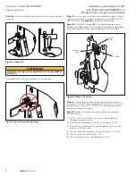
Page 1: ...FOLLOW THESE STEPS FOR ALL PROCEDURES DESCRIBED IN THIS INSTRUCTION LEAFLET COULD RESULT IN DEATH BODILY INJURY OR PROPERTY DAMAGE WARNING THE INSTRUCTIONS CONTAINED IN THIS IL AND ON PRODUCT LABELS H...

Page 2: ...cket drive 10 mm socket 2 Phillips head screwdriver 1 7 16 inch 36 mm hole saw 3 32 hex key 9 64 hex key Needle nose pliers Arbor press bench vise or equivalent a Spring puller such as Moody Tool item...

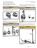
Page 3: ...ck and then mount to lock mounting plate C with the knurled nut IMPORTANT DO NOT INSERT KEY Key lock A Bushing B Knurled nut Kirk lock mounting plate C Figure 3 Step 2 Step 3 Put torsion spring D on g...

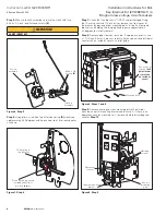
Page 4: ...er is OPEN and discharged Using the 10 mm socket and 1 4 inch driver remove the front cover of the breaker by loosening four mounting bolts six bolts if four pole breaker and holding the charging hand...

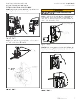
Page 5: ...lled lock assembly Machine screws M Figure 11 Step 11 IMPORTANT FAILURE TO INSTALL EXTENSION SPRING AS SHOWN WILL CAUSE MALFUNCTION OF THIS KIT Step 12 Connect extension spring N between the interlock...

Page 6: ...accept tapping screw Q replace it by prying off existing e clip and sliding off the trip lever Install new trip lever O and install e clip P Trip lever O E clip P Tapping screw Q Figure 16 Steps 13 an...

Page 7: ...IMPLIED INCLUDING WARRANTIES OF FITNESS FOR A PARTICULAR PURPOSE OR MERCHANTABILITY OTHER THAN THOSE SPECIFICALLY SET OUT IN ANY EXISTING CONTRACT BETWEEN THE PARTIES ANY SUCH CONTRACT STATES THE ENTI...

Page 8: ...ed in USA Publication No IL2C13761H11 Z23948 March 2020 Eaton is a registered trademark All other trademarks are property of their respective owners Installation instructions for Kirk Key Interlock Ki...

Reviews: