5
Instruction Leaflet
IL2C13761H11
Effective March 2020
Installation instructions for Kirk
Key Interlock Kit (2C12891G21) in
Magnum low-voltage circuit breakers
EATON
www.eaton.com
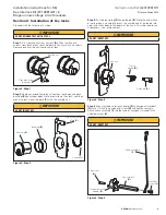
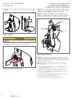
Step 10:
Snap interlock arm assembly
(L)
into place on shaft, with
steel spring flush against mechanism side plate.
(L)
Figure 10. Step 10
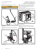
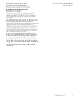
Step 11:
Mount lock/interlock assembly to plate mounting bracket
with three machine screws
(M)
supplied.
Lock mounting
plate (C)
Installed lock
assembly
Machine
screws
(M)
Figure 11. Step 11
IMPORTANT
FAILURE TO INSTALL EXTENSION SPRING AS SHOWN WILL CAUSE
MALFUNCTION OF THIS KIT.
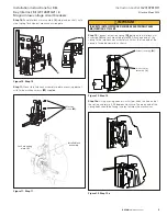
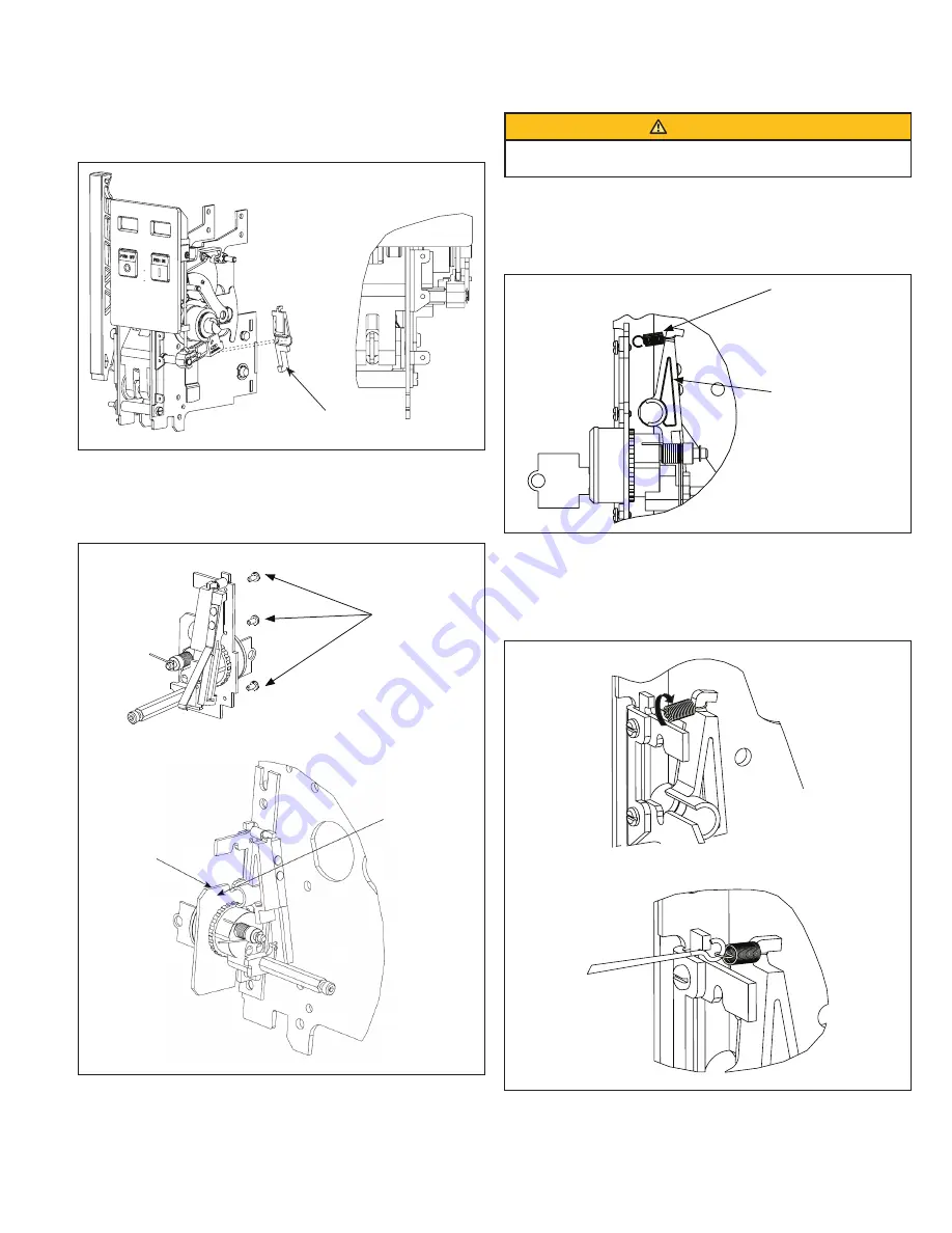
Step 12:
Connect extension spring
(N)
between the interlock arm
assembly
(L)
and lock mounting plate
(C)
. Attach one end of the
spring to the interlock arm assembly such that the free end of the
spring is facing downward, as shown.
Extension spring
(N)
Interlock arm
assembly
(L)
Figure 12. Step 12
Step 12a:
Using a spring hook or similar tool, hook the free end of
the spring and rotate it 90 degrees clockwise. The open end of the
spring hook should be facing inwards towards the mechanism.
Figure 13. Step 12a


